Difference between revisions of "FADC timing"
m |
m |
||
| Line 2: | Line 2: | ||
[[Image:fadcexpected.jpg|thumb|none|400px|figure 1: Expected fADC output. ADC channels as a function of time (ns)]] | [[Image:fadcexpected.jpg|thumb|none|400px|figure 1: Expected fADC output. ADC channels as a function of time (ns)]] | ||
| − | Unfortunately this is not seen in most cases. It turns out that in 1/3 of the cases the rising edge starts at 1025 ns instead of 1040 ns. Also INDEPENDENT of the position off the rising edge the signal is kind of cut of at the end. My theory is that the start pointer returned by the flash ADC is not always the correct one. I already knew that the rising edge can jump 15ns in time but the behavior at the end of the time spectrum was brought to my attention by Gregg Franklin and Diana Parno who is using a similar fADC for the HALL-A polarimeter upgrade and they use different software than I do. An example of more common spectra is shown in figure 2. | + | Unfortunately this is not seen in most cases. It turns out that in 1/3 of the cases the rising edge starts at 1025 ns instead of 1040 ns. Also INDEPENDENT of the position off the rising edge the signal is kind of cut of at the end. My theory is that the start pointer returned by the flash ADC is not always the correct one. I already knew that the rising edge can jump 15ns in time but the behavior at the end of the time spectrum was brought to my attention by Gregg Franklin and Diana Parno who is using a similar fADC for the HALL-A polarimeter upgrade and they use different software than I do. An example of a more common spectra is shown in figure 2. |
[[Image:notexpected.jpg|thumb|none|400px|figure 2: Expected fADC output. ADC channels as a function of time (ns)]] | [[Image:notexpected.jpg|thumb|none|400px|figure 2: Expected fADC output. ADC channels as a function of time (ns)]] | ||
Revision as of 17:20, 1 April 2008
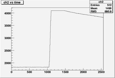
The following test was performed: a 3 us long positive block pulse was fed into the fADC AND used as a trigger. The trigger was setup so that when the 3 us long pulse is fed into the fADC the stop signal came 1040 ns after the rising edge of the long pulse. The fADC ran at 200 MHz internal clock. The expected fADC time spectrum is shown in figure 1.
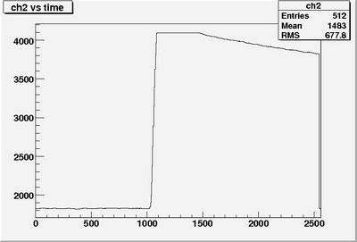
Unfortunately this is not seen in most cases. It turns out that in 1/3 of the cases the rising edge starts at 1025 ns instead of 1040 ns. Also INDEPENDENT of the position off the rising edge the signal is kind of cut of at the end. My theory is that the start pointer returned by the flash ADC is not always the correct one. I already knew that the rising edge can jump 15ns in time but the behavior at the end of the time spectrum was brought to my attention by Gregg Franklin and Diana Parno who is using a similar fADC for the HALL-A polarimeter upgrade and they use different software than I do. An example of a more common spectra is shown in figure 2.

