Difference between revisions of "Testing of PMT dividers"
| Line 42: | Line 42: | ||
Image:ccal_prot_cables4.jpg | Fig. 4 - Patch panels: LV distribution for the 5x5 prototype (right) | Image:ccal_prot_cables4.jpg | Fig. 4 - Patch panels: LV distribution for the 5x5 prototype (right) | ||
Image:ccal_prot_cables5.jpg | Fig. 5 - Patch panel from the outside of the CCAL (the MPOD connector is on the left) | Image:ccal_prot_cables5.jpg | Fig. 5 - Patch panel from the outside of the CCAL (the MPOD connector is on the left) | ||
| + | </gallery> | ||
| + | |||
| + | |||
| + | '''Tuning dividers after the CCAL beam test ''' | ||
| + | <gallery> | ||
| + | Image:before_saturation.jpg | Fig. 1 Original base before saturation | ||
</gallery> | </gallery> | ||
Revision as of 09:27, 26 May 2023
New version of the active base
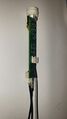
Fig. 1 Connectors on the new base
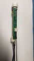
Fig. 2 Connectors on the new base
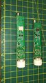
Fig. 3 Extension of the PCB to accommodate the new connector


Bench tests
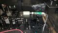
Fig. 1 Setup for testing PMT dividers
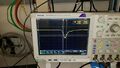
Fig. 2 Bypassed amplifier, small amplitude
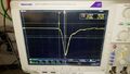
Fig. 3 Bypassed amplifier, large amplitude
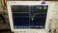
Fig. 3 Amplifier gain 3, small amplitude


Installing 5x5 prototype on CCAL
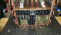
Fig. 1 - Front view of the CCAL
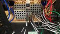
Fig. 2 - Rear view of the CCAL
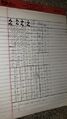
Fig. 3 - List of modules installe


Cables, and patch panels
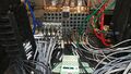
Fig. 1 - Cables connected to the FCAL2 dividers (signal, HV, and LV)
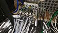
Fig. 2 - Cables connected to the FCAL2 dividers (signal, HV, and LV)
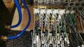
Fig. 3 - Closer look of dividers
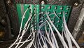
Fig. 4 - Patch panels: LV distribution for the 5x5 prototype (right)
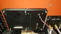
Fig. 5 - Patch panel from the outside of the CCAL (the MPOD connector is on the left)


Tuning dividers after the CCAL beam test
- Before saturation.jpg
Fig. 1 Original base before saturation