Difference between revisions of "FADC timing"
From GlueXWiki
m |
m |
||
| Line 1: | Line 1: | ||
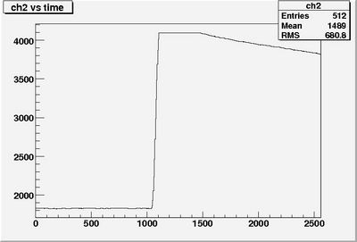
| − | The following test was performed: a 3 us long positive block pulse was fed into the fADC. The trigger was setup that | + | The following test was performed: a 3 us long positive block pulse was fed into the fADC AND used as a trigger. The trigger was setup so that when the 3 us long pulse is fed into the fADC the stop signal came 1040 ns after the rising edge of the long pulse. The fADC ran at 200 MHz internal clock. The expected fADC time spectrum is shown in figure 1. |
| − | ran at 200 MHz internal clock. | + | [[Image:fadcexpected.jpg|thumb|none|400px|figure 1: Expected fADC output.]] |
| − | The expected fADC time spectrum is shown in figure 1. | + | |
Revision as of 16:51, 1 April 2008
The following test was performed: a 3 us long positive block pulse was fed into the fADC AND used as a trigger. The trigger was setup so that when the 3 us long pulse is fed into the fADC the stop signal came 1040 ns after the rising edge of the long pulse. The fADC ran at 200 MHz internal clock. The expected fADC time spectrum is shown in figure 1.
