Sweep magnet 2
Contents
Sweep Magnet #2
The magnet which we will use for the second sweep is a DW magnet on permanent load from the FEL group.
The drawings set for the magnet is here: | Dw Magnet
Characteristics of DW Magnets
| Parameter | Value |
|---|---|
| Design Field | 0.248 T |
| Effective Length | 0.408 m |
| Max Current | 200 A |
| Max Voltage drop | 11 V |
| LCD water | 0.64 gpm @ 80 psi for a 21° F rise |
| Magnet gap | 2.00 inches |
| Gap Width | 8.4 inches |
Specific data for DW002 (dipole in the alcove):
| Parameter | Value |
|---|---|
| Magnet Design Field | 1.32 KGauss |
| Design Resistance at running temperature | 0.052Ω |
| Voltage, warm, at design current | 10.18 V |
| Power at running temperature | 2.01 KW |
| Water flow at 80 psi | 0.64 gpm |
| Pole tip gap | 2.125 inches |
| Pole tip width | 6 inches |
| Design field length | 16.06 inches |
| Magnet Assembly Drawing Number | 07133-E-1001 |
Sweep Magnet #2 Power supply
I asked Bill Merz to recommend a power supply for this magnet. He suggested a few companies Original mail from Bill . Based on this I decided to base the preliminary design on the Genesys power supply which is the newer version of the lambda power supply.
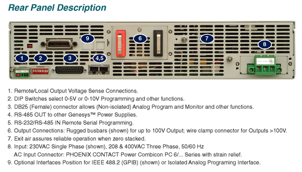
The Genesys 15-220 is a 2U high 15V 220A 3.3kW remotely programmable power supply. The model number is Gen 15-220- -1P230 for the 230V single phase version.
The back of the power supply is shown below. The power supply can be controlled by either RS-232 or using analog control lines on the J1 connector. A proposed system design is also presented below based on RS-232 readout. The RS-232 connector is connector 5 in the figure and the analog programming connector is number 3.
The manual for the Genesys power supply is found here.Manual pdf
Sweep2 System Design
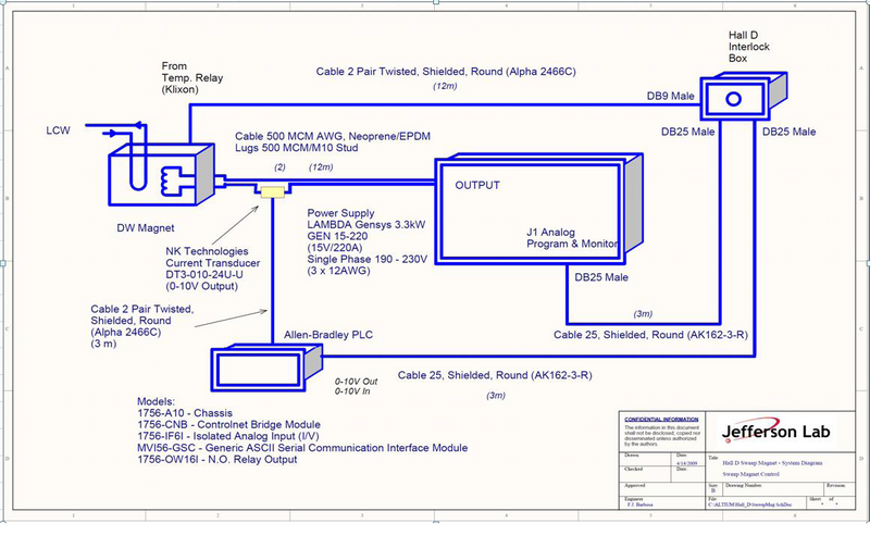
The following figure is an overview of the system design for the sweeping magnet #2 in the collimator cave. This design is based on the Genesys model power supply and an Allen Bradley PLC control via rs-232. The magnet current is monitored by two sensors. The voltage and current can be monitored using the analog out plug on the back of the power supply and an independent current meter. A CAT6 cable with rj45 connectors needs to be added between power supply and the Allen Bradley PLC.
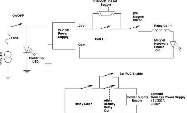
A first proposal for the interlock for the magnet is shown below. This system will require someone to push a button to enable the power supply and in the event the power supply fails for some reason it will not automatically switch back on. It will also disable the power supply in the temperature switch opens and require a manual reset. The connections to the PLC from the analog connector should be added.
The source file for the figure is here. DW_Enable.fig
Magnet Interlock Box
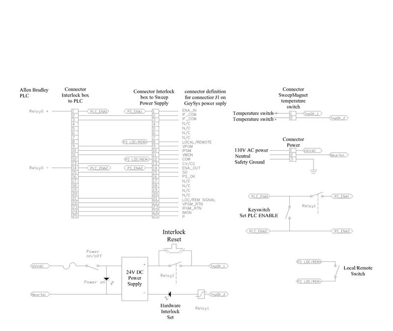
A proposal for the schematic for the interlock box for the magnet is shown below. The ACAD source file for this proposal is here
System Design Summary Document
The design is summarized in the following Excel document. Excel summary.


