Plan for mapping PS magnet
From GlueXWiki
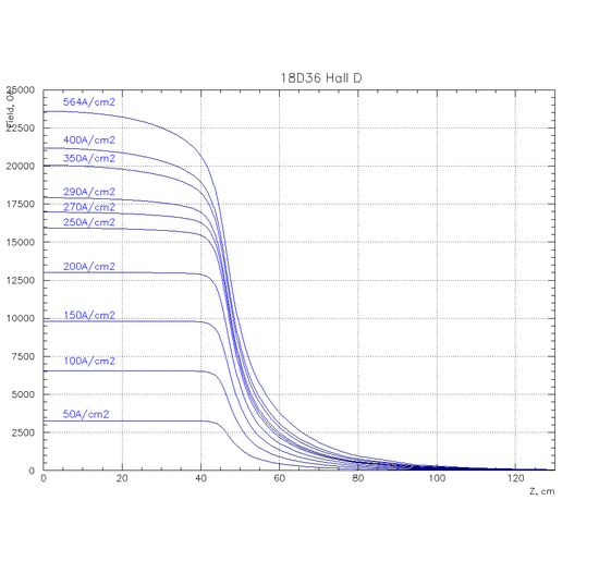
TOSCA simulation provided by S. Glamazdin. Field profile along the Z axis. Z = 0 cm is at the center of the magnet.
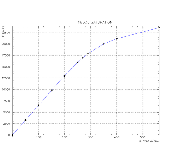
Saturation
Mapping Requirements
Coordinate system
- The origin (0,0,0) is the geometric center of the magnetic poles, located in the middle of the gap.
- Z axis is along the beam and points along the photon beam direction
- Y is vertical
- X is perpendicular to the beam points to the Hall D south wall
Mapping Regions
Downstream end of the magnet
- 0 cm < Z < 90 cm
(1st measure fringe field for the maximum Z range allowed by the mapper)
- -22 cm < X < 22 cm
- Z = -1 cm, 0 cm, 1 cm, (3 cm)
Upstream end of the magnet
- -90 cm < Z < 0 cm
- -5 cm < X < 5 cm
- Y = -1 cm, 0 cm, 1 cm, (3 cm)
Step size
- 1 cm in X and Z
Mapping Fields
- 1.8 T
- 1.9 T
- 1.5 T
- ( 1 T)
Mapping procedure
- Map the fild along the beamline for B = 1.8 T (Y = 0) and compare with TOSCA
- Make a 2-D map for various fields: B = 1.8 T, 1.9 T, 1.5 T (1 T?)
- Make a 2-D map for B = 1.8 T at Y = -1 cm and 1 cm. We'll decide whether a 3D map is needed for other fields when we get data
- Can we rotate 2 Hall probes to measure Bz and Bx ?

