Click for high resolution pictures
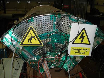
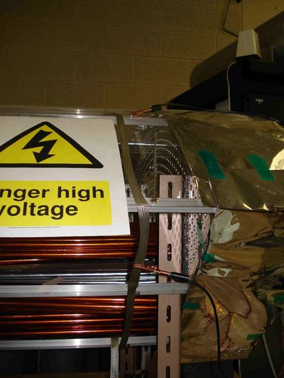
Picture 1: upstream endplate, ground connections can be seen (wires ending in alligator clamps on top of the CDC)
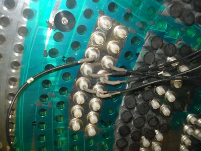
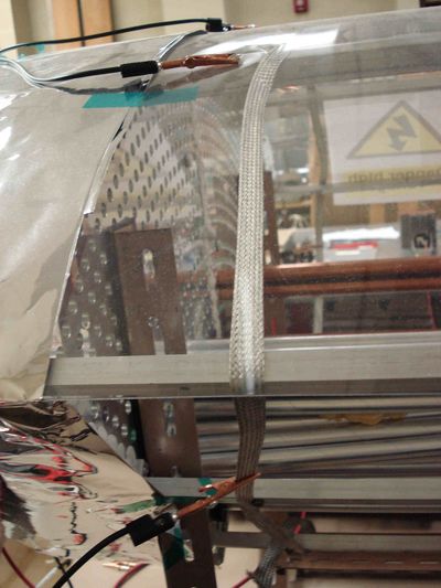
Picture 2: connection of the straw-tube-wire with signal/HV cable: the wies ends in the gold colored crimp pin, over that pin a gray conductive rubber hose is moved, the signal/HV cable is moved inside the conductive rubber hose (for close ups of this connections see picture 3 and 4).

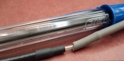
Picture 3: Close up of the conductive rubber - signal/HV cable connection (not connected).
Picture 4: Close up of the conductive rubber - signal/HV cable connection (connected).
Picture 5: HV/signal cables and feed-through.
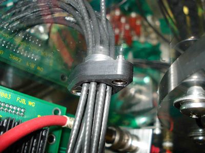
Picture 6: Close-up of the feed-through.
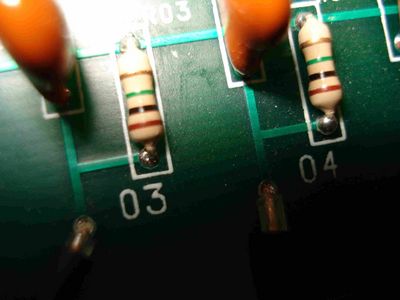
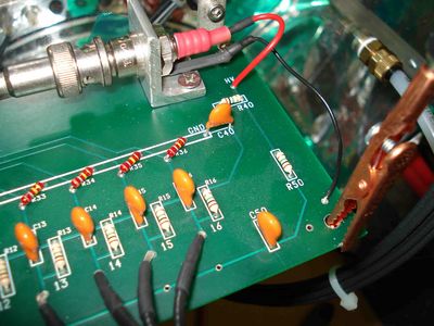
Picture 7: Signal/HV cable connection with the HV distribution board (close-up).
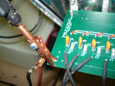
Picture 8: Ground connections at the HV distribution board (left alligator clamp).
Picture 9: Ground connections at the HV distribution board (right alligator clamp).
Picture 10: Ground connections (alligator clamps) at the end-plate (left side)
Picture 11: Ground connections (alligator clamps) at the end-plate (right side)
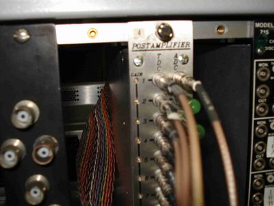
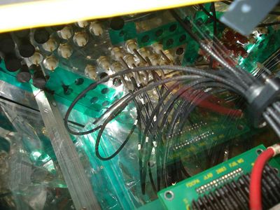
Picture 12: Flatcable going to the postamp, the LEMO cables go to the fADCs


