Minutes-7-10-2014
July 10, 2014 FDC+CDC meeting
Agenda
- Gas system
- DAQ (Beni)
- CDC status CDC noise studies (Mike, Beni)
- FDC status CDC raw data, FDC raw data, [1] (Lubomir)
- FDC noise studies, [2] (Luke)
- Electronics (Chris, Nick)
- Engineering (Bill)
- Other
![[2]](http://www.jlab.org/Hall-D/detector/fdc/commissioning/200Hznoise.JPG)
Instructions for Bluejeans meeting connection
FDC meeting ID: 290664653
Minutes
Participants: Curtis, Naomi (CMU), Luke, Eugene, Dave, Chris, Nick, Simon, Mike, Beni, Fernando, and Lubomir (JLab).
Gas system
- Last Thursday after the FDC meeting Dave and Lubomir connected the power of the gas controls in the gas room to a UPS. When the power was restored the 4-20mA setting of the two masters were different (40mA as usual), but also the settings of one slave channel did change, that never happened before. Dave will see if he can read the settings and either restore them correctly, or issue an alarm. This has to be discussed also with Hovanes.
- On Saturday the switch on the CO2 bottles didn't work when one set of bottles got empty; it was supposed to switch to the full set of bottles. For one-two hours there was no CO2 flow into the FDC mixing tank, and 0.2l/m (instead of 0.9) was going into the CDC mixing tank. The bottom half of the CDC and 25% of the FDC channels tripped. Dave can implement an alarm, but everybody agrees some kind of a messaging system is needed, as well. Scott contacted the gas company to replace the switch. This switch was working before, and we have the same switch for the Argon bottles.
DAQ
- Beni: The attempt to read synchronously the BCAL and the CDC failed. It's not clear why, the ROCs where receiving the data but then they got lost somewhere. Will try it again tomorrow.
- Beni: there's a problems with the relation between the pedestal positions and the DAC values in the fADC. The relation is different for the CDC and the FDC. For the CDC the pedestals are at ~500 and all the DAC values are set to 0x9000 (hex), and for the FDC the pedestals are at ~1000 but the DAC values are set all at 0x8000 (see raw data plots linked to item 4). Fernando explained this by the difference in the pre-amp gains (factor of 4).
CDC update
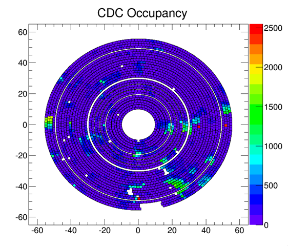
- Mike studied the noise in the CDC using raw fADC data. He applies a negative threshold (below the pedestal) and plots all the channels that pass the threshold as function of the sample number: there's clear correlations between the channels. The positions of these noisy channels is shown in the plot attached: mostly at the 6-9 o'clock sector when looking downstream.
FDC update
- Lubomir looked at the raw fADC data: plots linked above represent the distributions of the ADC values (from all the samples) as function of the channel. The plots are very useful since one can identify different kinds of problems: noisy channels when the area below the pedestal is populated, missing bit (like in the CDC plot ch.63), detector problem when the signals are small (like chan.71 in the FDC plot), connection issue when there's only a thin pedestal. Another problem is like ch.69 FDC plot: there's no pedestal visible, all values are overflown, however, if you look with a scope with differential probe we do see normal signals. If you connect another "good" cable to the same fADC connector everything is OK. What is then the difference between the fADC and the differential probe? Is this problem related to the pedestal problem Beni discussed above?
- Summary of these observation are shown in a spreadsheet linked above (only half of the crates are included so far). The number of bad detector channels is about the same as we had right after the installation as studied with a scope.
- Luke showed his studies (linked) of the noise in the FDC using a scope. He was looking for similar correlated noise that is seen in the CDC. This kind of noise is well visible only on these long strip that have short strips next to them (due to having ground from both sides of the frame). Luke's summary: most of the noise in the first and second package and mostly in the outer cells (one and six), frequencies 200kHz, 80kHz and 40kHz, amplitudes 10-15mV. Interestingly, if the cable is not well plugged into the adapter card, one can see the same noise on all the channels and the noise increases when the card is close to the VME crates (see picture).
Engineering
- Bill (not at the meeting): the microscope holder for the cathode scan is ready. Need to connect the motor the stage and to wire the motor controller and the stoppers (Dave). Luke will work on the scanning project.