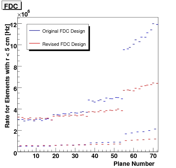
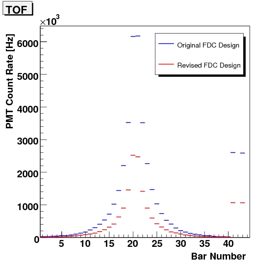
Impact of FDC Design on Noise Rates
The active regions of the FDC place a notable amount of material in the beam line that acts as scattering medium for generation of beam related backgrounds.
On May 15, 2007 Richard Jones updated the FDC geometry according to this message:
I have taken the new materials specifications for the CDC and FDC from gluex-doc-805 and implemented the changes in hdds. The modified geometry is now the latest release in subversion. The following changes have been made:
- Reduce the FDC cathode plane Kapton thickness from 50 to 25 microns.
- Reduce the FDC cathode strip copper layer from 5 microns to 1 micron.
- Remove rohacell backing on cathode strip planes in the active region. This also gets rid of the two layers of epoxy that bond the rohacell to the Kapton on one side, and the mylar on the other.
- Reduce the mylar film thickness from 25 microns to 5 microns with 0.5 microns of aluminum on one side. +
- Change chamber gas mixture to 40/60 Ar/C02.
- New heterostructure for FDC support frames, as per gluex-doc-800.
- Replace CDC aluminum downstream plate with carbon fiber / epoxy composite.
- Reduce the CDC downstream plate from 6mm to 4mm thickness.
+ This item was revised with input from Simon to be 6.3 microns of mylar with 0.2 microns of aluminum
Using revision 2568 of the SVN repository which incorporated all changes to the geometry listed above the following plots for background rate in the FDC and TOF were generated to explore the impact of material revisions on noise rate.

