First Tests in Hall-D
From GlueXWiki
This part describes initial tests of the FDC during cabling as part of the installation in Hall-D
- Low Voltage: The LV crate U2-2-BOT (MAC: 00-50-C2-2D-CE-6F) provides all the bias voltage for all preamp cards (cathode strips and anode wires). The controls and GUIs are based on epics and CSS (control system studio). During installation of the LV cables the current read-backs in the LV GUI are used to verify proper connection (0.4x A for each preamp card).
- Monitoring: To run and monitor the GUIs required for the test a computer is installed in the hall connected to the slow control network. The computer is called "joebesser" (MAC: 00-07-E9-17-F7-A6) it runs a 32 bit redhat5 operating system and will mount the "/group/halld" disk.
- Code: The current programs used to test the ADC pedestals (random trigger) and TDC-cable-preamp chain (with built in pulser) are located under "/group/halld/Subsystems/fdc/daq/linux/code". Below that directory structure the code for running the tests on the readout controller and the code for subsequent analysis of the data. Note that environment variables need to be set correctly and have to be adapted to the hall-d conditions. Currently the code has been compiled and tested on wilma.jlab.org(desktop) and rocfdc1.jlab.org(ROC) in the EEL.
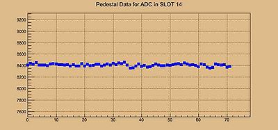
- ADC pedestal test: the codes are in ./code/ADCtests/src to run on the ROC while the data from the ROC is currently written to ./code/ADCtests/DATA and to analyze the data. Once deployed in the Hall the data this may be changed and the data may be written to the halld file system. The functionality of the code is as follows:
- How to run: src/readout/pedestalTest will run on the ROC. It requires at least one command line option -S # where # means the slot number of the ADC to be tested. Running the code without any command line parameter will give the results below. The data is written into an ascii file that can be visualized by running the code src/analyze/viewpeds -S # again the slot number is mandatory. At the same time it will create a pdf file for future reference.
- ADC pedestal test: the codes are in ./code/ADCtests/src to run on the ROC while the data from the ROC is currently written to ./code/ADCtests/DATA and to analyze the data. Once deployed in the Hall the data this may be changed and the data may be written to the halld file system. The functionality of the code is as follows:
./pedestalTest
      JLAB f125ADC pedestal Tests
      ----------------------------
      usage: pulserTestNew [Options]
             -S #   slot number of ADC to be used in test (default 4)
             -T #   Trigger timing offset default is 30
             -N #   Number of triggers default is 1000
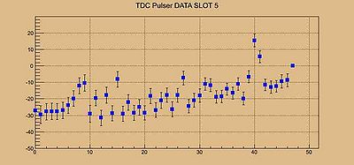
- TDC pulser test: the codes are in ./code/TDCpulserTest/src to run on the ROC while the data from the ROC is currently written to /code/TDCpulserTest/DATA and to analyze the data. The functionality of the code is as follows:
- How to run: src/ROCreadout/pulserTestNEW will run on the ROC. It requires at least one command line options -S # where # means the slot number of the ADC to be tested. Running the code without any command line parameter will give the results below. To analyze the data run the code src/analyze/pulsertest -S #. The data is written into a root file (you need root!) in the form of two histograms. A two dimensional with the vertical axis the channel number and the horizontal axis TDC counts and a one dimensional histogram with the x-axis the channel number and the y-axis the mean of the TDC counts with error bars the RMS of the distribution of that channel. The highest channel number that has data is used as TDC reference.
- TDC pulser test: the codes are in ./code/TDCpulserTest/src to run on the ROC while the data from the ROC is currently written to /code/TDCpulserTest/DATA and to analyze the data. The functionality of the code is as follows:
./pulserTestNEW
      JLAB f1tdc pulser Tests
      ----------------------------
      usage: pulserTestNew [Options]
            -S #   slot number of TDC to be tested REQUIRED!!!!
            -P #   DAQ value for pulser default is 400
            -T #   Trigger timing offset default is 30
            -N #   Number of triggers default is 1000
            -D     DEBUG on

