Detector Material Budget in the Forward Direction
Following the recommendations from the Drift Chamber Review of 3/2007, a number of ideas have been considered for reducing the amount of material seen by forward-going particles [1,2]. These ideas have recently coalesced into one concrete proposal from the CDC team and two options from the FDC team. These modifications are relative to the baseline CD2 design that was presented at the Drift Chamber Review [3]. The CDC modification is to replace the downstream CDC end plate, which was 6 mm of aluminum in the baseline design, with a lighter plate made of a carbon fiber composite 4 mm thick. The FDC options involve removing some of the material in the active region associated with the cathode planes and reducing the material in the chamber support structure. For a detailed description of the FDC options, see Material specifications for FDC Redesign.
Simulations
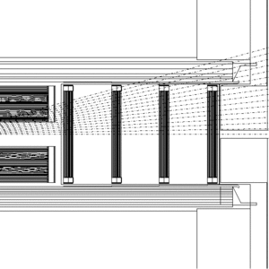
To validate the new simulation geometry that implements these modifications, three distinct simulations have been created for comparison.
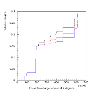
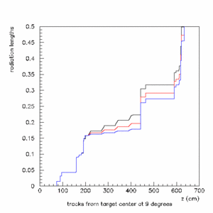
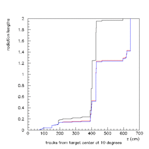
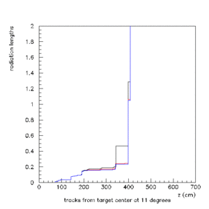
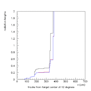
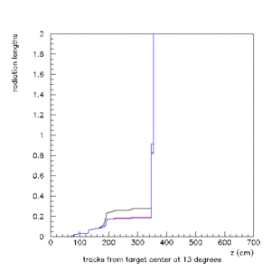
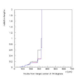
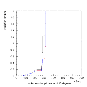
- Option 0: the CD2 baseline, presented at the DC review.
- Option 1: modified CD2 end plate and FDC option 1.
- Option 2: modified CD2 end plate and FDC option 2.
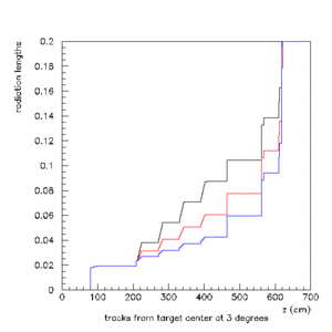
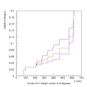
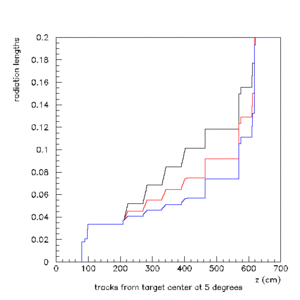
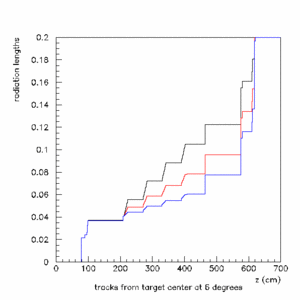
All other aspects of the geometry remain in the baseline configuration in order to isolate the effects of the drift chamber modifications. Linear tracks have been generated at integer values of the polar angle (0°, 1°, 2°, ... 15°) originating in the center of the target. It was convenient to use neutrinos so as to eliminate interactions. Fig. 1 at the right shows the traces of the neutrinos as they pass through the detector in the forward region drift chambers. The dash-dotted lines emerging from the center of the target are the paths along which the detector material was integrated.
Results
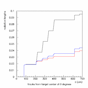
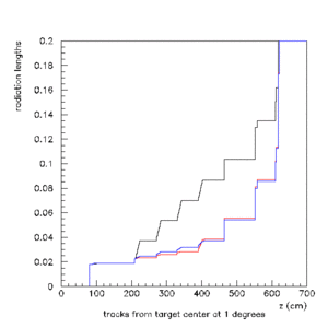
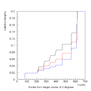
The following figures show the accumulated material along the particle trajectories shown in Fig. 1, measured in radiation lengths. Option 0 is in black, option 1 in red, and option 2 in blue.
 (eps figure)] |
 (eps figure)] |
 (eps figure)] |
 (eps figure)] |
 (eps figure)] |
 (eps figure)] |
 (eps figure)] |
 (eps figure)] |
 (eps figure)] |
 (eps figure)] |
 (eps figure)] |
 (eps figure)] |
 (eps figure)] |
 (eps figure)] |
 (eps figure)] |
 (eps figure)] |
References
- D.S. Carman and S. Taylor, "Drift Chamber Material Budget", gluex-doc-805, April, 2007.
- S. Taylor, "A proposal to reduce the FDC support material thickness", gluex-doc-800, April, 2007.
- R.T. Jones, "Detector Models for GlueX Monte Carlo Simulation: the CD2 Baseline", gluex-doc-732, January, 2007.