Tagger Magnetic Field Mapping
From GlueXWiki
Contents
Mapping requirements
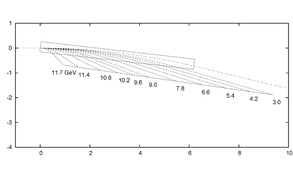
- We need to map every region of the field where electrons are transported, but can omit corners where no trajectories go. I attach a crude picture of electron orbits. Maybe Sascha has a better one.
- By my previous experience ray-tracing in the Hall B tagger magnet (6 cm gap), I would propose the following.
- Uniform field region inside gap (at least 10 cm or 4" away from a field boundary:
- 1" by 1" grid
- In the vicinity of the long field boundary:
- 1" (parallel to edge) by 0.25" transverse from -10 cm inside to +15 cm outside
- 1" (parallel to edge) by 1" transverse from +15 cm to +30 cm outside
- In the vicinity of the entry face and the full-energy beam exit, cover a region at least 6" (i.e. +/- 3") wide around the trajectories:
- 1" by 1" from 30 cm to 15 cm outside,
- 1" by 0.25" transverse from 15 cm outside to 10 cm inside
- Uniform field region inside gap (at least 10 cm or 4" away from a field boundary:

- A step of 0.25" near the field boundary means that the maximum field variation per step (which occurs just inside the nominal field boundary) is about 15%. This should be acceptable. If the time required for the above is excessive, we could take 2" steps parallel to the long field edge instead of 1".
Proposal from Tim Whitlatch
We are currently planning 1 cm steps all along the transverse direction and 2.5 cm steps along the long edge. This is what our fixture is designed to do since we have multiple hall probes 1 cm apart. It appears we can cover all your orbits shown.
Mapping coordinate system
Fields at which maps should be taken
Dan Sober proposes mapping the dipole at the following central field values:
- 6 kG
- 9 kG
- 12 kG
- 14 kG
- 15 kG
- 16 kG
- 17 kG