Difference between revisions of "TAGH PMT testing"
From GlueXWiki
| Line 1: | Line 1: | ||
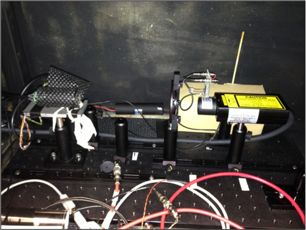
| − | [[ | + | [[Image:PSL_in_light_tight_box.png|600px]] |
After PMT leads and cables have been soldered to PCBs: | After PMT leads and cables have been soldered to PCBs: | ||
Revision as of 21:32, 29 September 2013
After PMT leads and cables have been soldered to PCBs:
- Place assembled PMTs in light-tight box and connect cables
- Verify that PMT, diffuser & attenuator stand, and Picosecond Laser are aligned
- Turn on HV and check monitored current, ramp up to 850 V
- Turn on Picosecond Laser (intensity scale to 1.5, freq. to 100 kHz)
- Check signals on oscilloscope, use measurement function to report min/max within the peak and integral
- Ramp laser frequency to 1 MHz, 2 MHz, 5 MHz, 10 MHz
- Repeat frequency scan for HV=900 V, 1000 V, 1100 V
- Check for break-down voltage and frequency
- Report results on excel sheet, save snapshots of scope signal
