Difference between revisions of "PMT rate tests"
(→PMT Rate Tests) |
|||
| Line 1: | Line 1: | ||
=== PMT Rate Tests=== | === PMT Rate Tests=== | ||
| + | |||
| + | We work here with two PMT assemblies H10534MOD. With the second assembly having a modified base with an additional pre-amplifier powered by the applied HV. | ||
==== Test with Reference PMT ==== | ==== Test with Reference PMT ==== | ||
Revision as of 13:18, 9 February 2017
PMT Rate Tests
We work here with two PMT assemblies H10534MOD. With the second assembly having a modified base with an additional pre-amplifier powered by the applied HV.
Test with Reference PMT
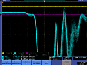
We test the signal output of the Hamamatsu PMT assembly H10534MOD. This is based on a 10 stage tube with two outputs. The test are performed using a reference PMT assembly in a laser beam where the light output of the laser is adjusted to generate a signal in the reference PMT assembly that is similar to what is seen by the PMTs in the TOF paddle at 1550V operating voltage. One can clearly see that at 5MHz the signal is distorted as the PMT can not handle the increased current. At this point the current in the PMT increased by about 3uA from initially 253uA at 1kHz. At 2MHz the current was still at 253uA.
- Reference PMT with laser output at 6.12
- PMT HV 1550V 1kHz
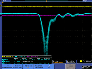
- PMT HV 1550V 1kHz zoom
- PMT HV 1300V 1kHz
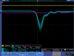
- PMT HV 1300V 1kHz zoom
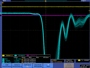
- PMT HV 1300V 2MHz
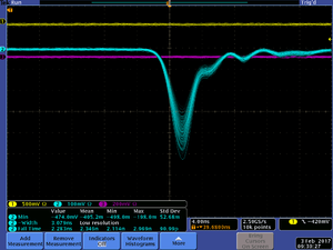
- PMT HV 1300V 5MHz
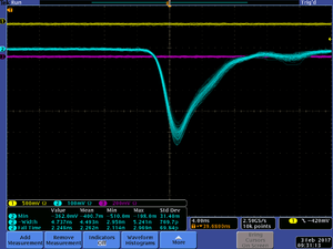
- PMT HV 1300V 10MHz
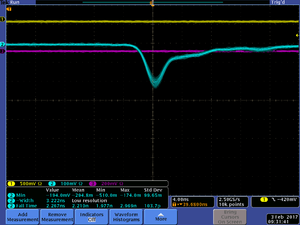
- PMT HV 1550V 1kHz


