Difference between revisions of "Minutes-6-20-2013"
m (Text replacement - "/halldweb1.jlab.org/" to "/halldweb.jlab.org/") |
|||
| (12 intermediate revisions by one other user not shown) | |||
| Line 2: | Line 2: | ||
= Agenda = | = Agenda = | ||
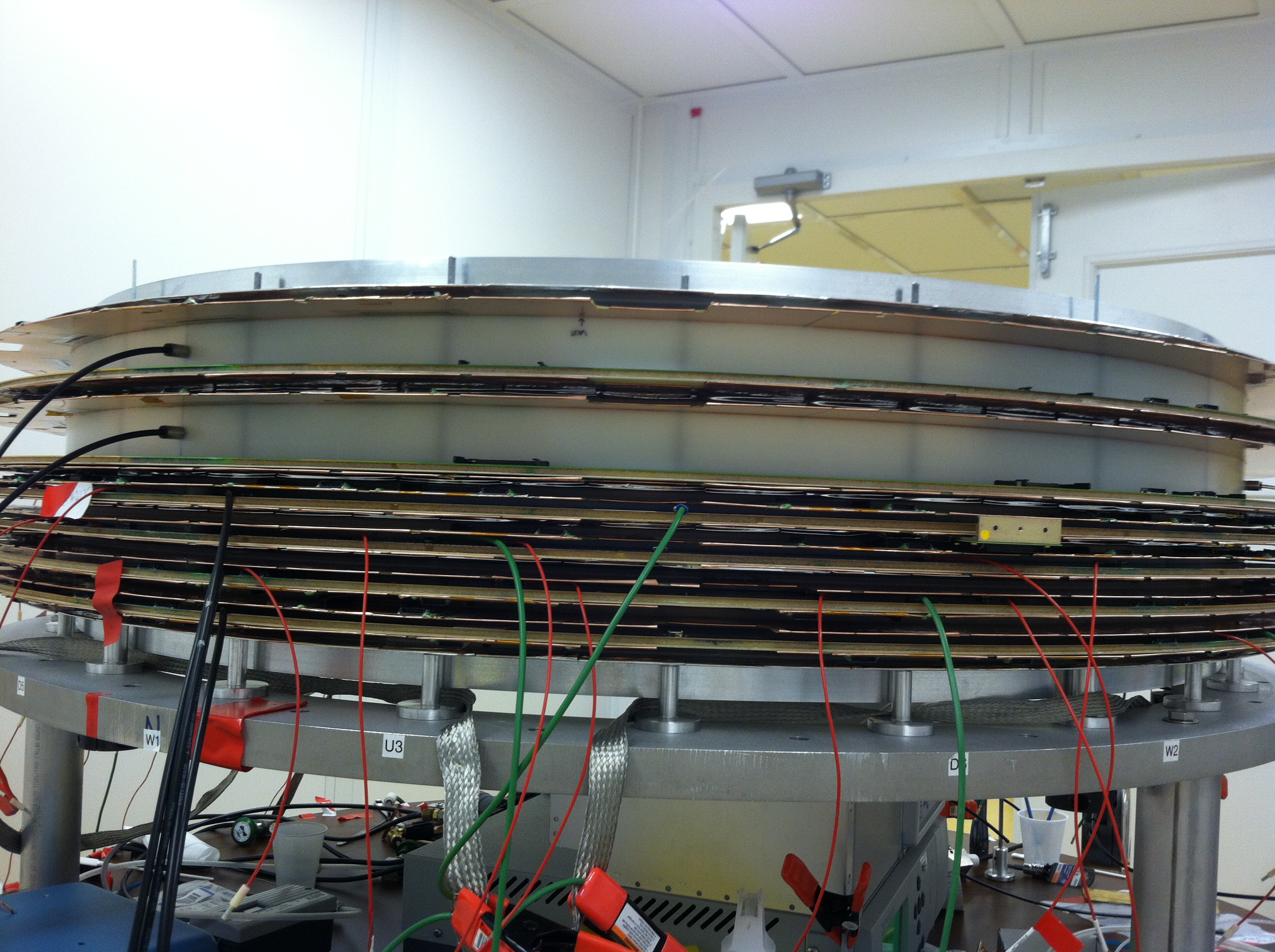
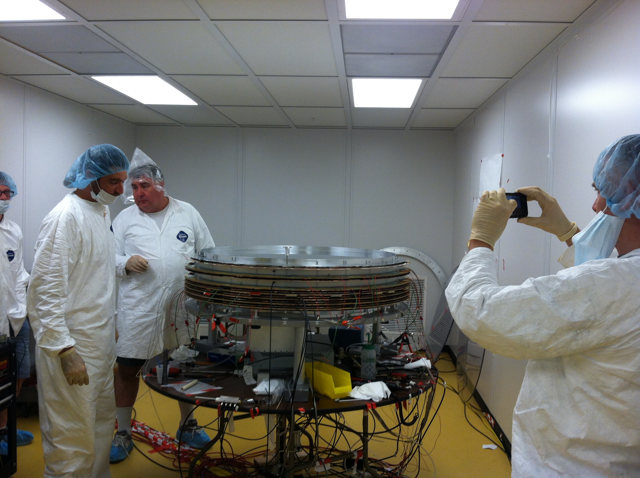
| − | # Production [http://www.jlab.org/Hall-D/detector/fdc/clucou/IMG_0516.JPG], [http://www.jlab.org/Hall-D/detector/fdc/clucou/IMG_0511.JPG] | + | # Production [http://www.jlab.org/Hall-D/detector/fdc/clucou/IMG_0516.JPG spare package installed], [http://www.jlab.org/Hall-D/detector/fdc/clucou/IMG_0511.JPG and the people around it] |
#* Spare package tests (Vlad) | #* Spare package tests (Vlad) | ||
#* Thicker cell results (Lubomir) [http://www.jlab.org/Hall-D/detector/fdc/clucou/tek.png], [http://www.jlab.org/Hall-D/detector/fdc/clucou/tek1.png], [http://www.jlab.org/Hall-D/detector/fdc/clucou/tek2.png], [http://www.jlab.org/Hall-D/detector/fdc/clucou/tek00010.png], [http://www.jlab.org/Hall-D/detector/fdc/clucou/tek00011.png], [http://www.jlab.org/Hall-D/detector/fdc/clucou/tek00000.png], [http://www.jlab.org/Hall-D/detector/fdc/clucou/tek00001.png], [http://www.jlab.org/Hall-D/detector/fdc/clucou/tek00002.png], [http://www.jlab.org/Hall-D/detector/fdc/clucou/tek00003.png], [http://www.jlab.org/Hall-D/detector/fdc/clucou/tek00004.png], [http://www.jlab.org/Hall-D/detector/fdc/clucou/tek00005.png] | #* Thicker cell results (Lubomir) [http://www.jlab.org/Hall-D/detector/fdc/clucou/tek.png], [http://www.jlab.org/Hall-D/detector/fdc/clucou/tek1.png], [http://www.jlab.org/Hall-D/detector/fdc/clucou/tek2.png], [http://www.jlab.org/Hall-D/detector/fdc/clucou/tek00010.png], [http://www.jlab.org/Hall-D/detector/fdc/clucou/tek00011.png], [http://www.jlab.org/Hall-D/detector/fdc/clucou/tek00000.png], [http://www.jlab.org/Hall-D/detector/fdc/clucou/tek00001.png], [http://www.jlab.org/Hall-D/detector/fdc/clucou/tek00002.png], [http://www.jlab.org/Hall-D/detector/fdc/clucou/tek00003.png], [http://www.jlab.org/Hall-D/detector/fdc/clucou/tek00004.png], [http://www.jlab.org/Hall-D/detector/fdc/clucou/tek00005.png] | ||
# Engineering (Bill) | # Engineering (Bill) | ||
# Electronics (Chris, Nick) | # Electronics (Chris, Nick) | ||
| − | # Full electronics test [https:// | + | # Full electronics test [https://halldweb.jlab.org/elog-halld/FDC FDC E-log] (Beni) |
# Other | # Other | ||
| − | |||
| − | |||
= Minutes = | = Minutes = | ||
| − | Participants: Bill, | + | Participants: Bill, Beni, Simon, Vlad, and Lubomir. Due to the PAC, magnet test going on at the same time, Wiener people coming on site, the turnout was low for this meeting. The meeting was in A110. |
== Production == | == Production == | ||
| − | - | + | - End of last week we installed the last cell of the last package (see the photos of the package and the happy people around it, attached above). Vlad tested the new cells and found no problems. The top two cells have 3.5 instead of 0.5cm spacer ring. When using iron source Vlad had to increase the HV by 100V to see approximately the same amplitudes as from the regular cells. Very interestingly the last two cells showed very low dark current ~20-30nA, compared to 200-800nA for the other cells. We are not sure why, just because these were the last two wire frames produced, or there's something else related to the special geometry of the cells. |
| − | - | + | - First signals on the scope with definitely visible individual clusters over a very long drift time (up to 15 usec) are attached above. We some minimal grounding we were able to lower the noise to <5mV. At the same time we increased the gas gain to about 2-3 x 10^5 by going up with the HV up to 2450/-500V ! |
| − | + | Amazingly the two cells were stable at this HV at least for several hours. Having such gas gain we were able to clearly see (scope pictures above) individual electrons corresponding to ~20-30 mV signal. On average we have two electrons per cluster, and really we see some single peaks, and some double/triple peaks separated due to the diffusion. On some of the plots two neighboring channels are shown (with different colors; we used a second differential probe from Fernando) and you can see the transition from one wire to another when the track crosses the filed region between the two wires. | |
| − | - | + | |
| + | - Plans: on Monday we will take the two gusset rings from the spare package since we will need them for a week to build the package spacers. For that, first we will replace the top gusset with a Lexan sheet, then will take the package out of the mounting table and put it upside down using some strong-back. Then we will replace the bottom gusset. After we are done with the spacers we will re-install the gusset rings in the same way. The spare package will go for testing in 126 after we are done with the third package there. The spacers will be installed between the packages and then we will do the practicing with the mock-up. | ||
== Engineering == | == Engineering == | ||
| − | - | + | - Bill started working on the fixture for the scintillators needed at the Hall for triggering: it is not a problem at all and will consists of unistruts along the cart attached to the cart frame. |
| − | + | ||
| − | + | ||
| + | - Bill was asked by Bruce Lenzer (suggested by Glen) to include the mock-up cabling in their QA plan, since this will verify that the cable density is correct and that there's enough space to the CDC and BCAL. Bill will write a short report after this exercise. | ||
| + | |||
== Full electronics tests == | == Full electronics tests == | ||
| − | - | + | - Beni now has the software to sparsify the data from the fADC in the ROC processors. Now he is taking long runs over the night and some results are shown in the E-log entries 110, 111. There you can see the raw signals (one plot per fADC), the profiles of the strips from all the planes connected (4 cells so far), and the wire positions as reconstructed from the strips. The reconstruction method is simplified so far, that's why you see a lot of noise in between the wire positions. |
| − | + | ||
| − | + | ||
| − | + | ||
| − | + | ||
| − | + | ||
| − | + | ||
| − | + | ||
| − | + | ||
| − | - | + | - Two fADC channels are not working properly and there are four strips where the problem is in the FDC. In the previous version of these plots there were ~10 missing strips. Vlad and Lubomir fixed all of them by unplugging/plugging the cards and sometimes releasing a little bit the screws on the clamps. Several of the channels were next to a manifold, but those were fixed. After that two strips re-appeared as problematic and two new strips showed problems. Beni suggested to spray the connectors with a cleaner to see if this will help. |
| − | - | + | - Plans: the new VXS crate is in 126 and Chris and Nick will install it soon. Next week when Cody is back Beni will take 12 more fADC125s. Then we will connect the last two cells with signal cables and will be able to take data from all the channels. |
--> | --> | ||
Latest revision as of 01:50, 1 April 2015
June 20, 2013 FDC meeting
Agenda
- Production spare package installed, and the people around it
- Engineering (Bill)
- Electronics (Chris, Nick)
- Full electronics test FDC E-log (Beni)
- Other
![[1]](http://www.jlab.org/Hall-D/detector/fdc/clucou/tek.png)
![[2]](http://www.jlab.org/Hall-D/detector/fdc/clucou/tek1.png)
![[3]](http://www.jlab.org/Hall-D/detector/fdc/clucou/tek2.png)
![[4]](http://www.jlab.org/Hall-D/detector/fdc/clucou/tek00010.png)
![[5]](http://www.jlab.org/Hall-D/detector/fdc/clucou/tek00011.png)
![[6]](http://www.jlab.org/Hall-D/detector/fdc/clucou/tek00000.png)
![[7]](http://www.jlab.org/Hall-D/detector/fdc/clucou/tek00001.png)
![[8]](http://www.jlab.org/Hall-D/detector/fdc/clucou/tek00002.png)
![[9]](http://www.jlab.org/Hall-D/detector/fdc/clucou/tek00003.png)
![[10]](http://www.jlab.org/Hall-D/detector/fdc/clucou/tek00004.png)
![[11]](http://www.jlab.org/Hall-D/detector/fdc/clucou/tek00005.png)
Minutes
Participants: Bill, Beni, Simon, Vlad, and Lubomir. Due to the PAC, magnet test going on at the same time, Wiener people coming on site, the turnout was low for this meeting. The meeting was in A110.
Production
- End of last week we installed the last cell of the last package (see the photos of the package and the happy people around it, attached above). Vlad tested the new cells and found no problems. The top two cells have 3.5 instead of 0.5cm spacer ring. When using iron source Vlad had to increase the HV by 100V to see approximately the same amplitudes as from the regular cells. Very interestingly the last two cells showed very low dark current ~20-30nA, compared to 200-800nA for the other cells. We are not sure why, just because these were the last two wire frames produced, or there's something else related to the special geometry of the cells.
- First signals on the scope with definitely visible individual clusters over a very long drift time (up to 15 usec) are attached above. We some minimal grounding we were able to lower the noise to <5mV. At the same time we increased the gas gain to about 2-3 x 10^5 by going up with the HV up to 2450/-500V ! Amazingly the two cells were stable at this HV at least for several hours. Having such gas gain we were able to clearly see (scope pictures above) individual electrons corresponding to ~20-30 mV signal. On average we have two electrons per cluster, and really we see some single peaks, and some double/triple peaks separated due to the diffusion. On some of the plots two neighboring channels are shown (with different colors; we used a second differential probe from Fernando) and you can see the transition from one wire to another when the track crosses the filed region between the two wires.
- Plans: on Monday we will take the two gusset rings from the spare package since we will need them for a week to build the package spacers. For that, first we will replace the top gusset with a Lexan sheet, then will take the package out of the mounting table and put it upside down using some strong-back. Then we will replace the bottom gusset. After we are done with the spacers we will re-install the gusset rings in the same way. The spare package will go for testing in 126 after we are done with the third package there. The spacers will be installed between the packages and then we will do the practicing with the mock-up.
Engineering
- Bill started working on the fixture for the scintillators needed at the Hall for triggering: it is not a problem at all and will consists of unistruts along the cart attached to the cart frame.
- Bill was asked by Bruce Lenzer (suggested by Glen) to include the mock-up cabling in their QA plan, since this will verify that the cable density is correct and that there's enough space to the CDC and BCAL. Bill will write a short report after this exercise.
Full electronics tests
- Beni now has the software to sparsify the data from the fADC in the ROC processors. Now he is taking long runs over the night and some results are shown in the E-log entries 110, 111. There you can see the raw signals (one plot per fADC), the profiles of the strips from all the planes connected (4 cells so far), and the wire positions as reconstructed from the strips. The reconstruction method is simplified so far, that's why you see a lot of noise in between the wire positions.
- Two fADC channels are not working properly and there are four strips where the problem is in the FDC. In the previous version of these plots there were ~10 missing strips. Vlad and Lubomir fixed all of them by unplugging/plugging the cards and sometimes releasing a little bit the screws on the clamps. Several of the channels were next to a manifold, but those were fixed. After that two strips re-appeared as problematic and two new strips showed problems. Beni suggested to spray the connectors with a cleaner to see if this will help.
- Plans: the new VXS crate is in 126 and Chris and Nick will install it soon. Next week when Cody is back Beni will take 12 more fADC125s. Then we will connect the last two cells with signal cables and will be able to take data from all the channels.
-->