Difference between revisions of "Minutes-6-16-2011"
(→Agenda) |
|||
| (8 intermediate revisions by the same user not shown) | |||
| Line 25: | Line 25: | ||
== Production == | == Production == | ||
| − | - The pictures linked above, show the configuration of the first chamber package and the testing set-up. After taking the wire frame form the vacuum chamber (vacuum went down to ~6 10^-6 tor) we checked that the frame was no longer conductive and we installed it again in the package. First we had Lexan sheet on the top, than we replaced it with the second cathode and the second end window. The package has no detectable gas leakage and we bubble it with a flow of 20-40 ccpm. On three of the HV sectors (out of four) we were able to apply HV up to 2300V and -500V sense/field with current less than 100 uA. The fourth HV sector shows high current so far: ~500 uA at 2000V/-500V. It may improve, but if not, it will require cleaning. In any case the chamber is operational and we tested all the channels with a scope with differential probe. In the moment we see signals from all the channels (both wires and strips) except one cathode channel on the bottom cathode which connectors are close to a metal pin. We suspect it was damaged when prying the wire frame with a screw driver when it was taken to be put in the vacuum chamber. The pins are very tight (compared to the prototype) and the only way to take a frame out was to rotate the pins while lifting the frame; for that you need | + | - The pictures linked above, show the configuration of the first chamber package and the testing set-up. After taking the wire frame form the vacuum chamber (vacuum went down to ~6 10^-6 tor) we checked that the frame was no longer conductive and we installed it again in the package. First we had Lexan sheet on the top, than we replaced it with the second cathode and the second end window. The package has no detectable gas leakage and we bubble it with a flow of 20-40 ccpm. On three of the HV sectors (out of four) we were able to apply HV up to 2300V and -500V sense/field with current less than 100 uA. The fourth HV sector shows high current so far: ~500 uA at 2000V/-500V. It may improve, but if not, it will require cleaning. In any case the chamber is operational and we tested all the channels with a scope with differential probe. In the moment we see signals from all the channels (both wires and strips) except one cathode channel on the bottom cathode which connectors are close to a metal pin. We suspect it was damaged when prying the wire frame with a screw driver when it was taken to be put in the vacuum chamber. The pins are very tight (compared to the prototype) and the only way to take a frame out was to rotate the pins while lifting the frame; for that you need to unscrew the hubs from the jig plate. Bill will work on designing pins that are easily removable. Before, there were also another two channels on the top cathode not showing signals but after bending a little the cathode periphery at the daughter card it started working (has to be investigated!). At the beginning of the tests most of the noise was coming from the chamber itself, but later it improved. Generally, the pick-up noise is much lower than on the full-scale prototype. Could be because of the new design cathode shielding, and/or because Blue Crab is less noisy than 126. |
| − | + | ||
| − | - | + | - Dave summarized the production progress on the spreadsheet linked above. Techs are working on the second and third cells that will be part of the first package. Remaining for cell#2: tomorrow Chris will put the second phase elements on the wire frame and then we will clean it manually with alcohol. Casey will glue the rigid-flexes. Anatoly is working on the flaps of one of the cathodes and the end windows. Mike and Tina are working on the gas spacer and next cathode foils. On Tuesday we can start assembling the package. Techs were working also on different tooling: Casey made lazy-Susan for attaching the cathodes and gluing rigid-flexes. Al and Caleb are testing/writing software for the new encoder. |
| − | |||
| − | |||
| − | |||
| − | |||
== Engineering == | == Engineering == | ||
| − | - | + | - Bill, Casey installed the new encoder and it will be used for third wire frame (stringing will start tomorrow). The monuments will be installed on the table later for the fourth chamber. |
| − | + | - Bill is waiting for the quotation of the Al gusset ring (it came at the of the day: ~$1200 per ring; we need 8). We discussed also possible lifting frame and covers for the package. Bill will design coverplates (out of g10) that will be attached to plastic threaded rods. Bill was also working on the procedures. | |
| − | + | ||
| − | - Bill is | + | |
== Electronics == | == Electronics == | ||
| − | - | + | - Tinned or un-tinned flex connectors: all the samples so far, both tinned and un-tinned, show no problems except one channel on the first sample showing connection to ground when you bend it (later it turned out it is a problem of the connector on the daughter board). So, we decided to have them tinned because: (1) the conductive tape gluing works better with tinned, due to the increased thickness of the contacts, and (2) because we can use standard soldering technique, if we have to. |
| − | - | + | - Chris started receiving signal cables (first CDC type) 75 per week. He will test them at 126 and store them somewhere there. |
== Chamber testing == | == Chamber testing == | ||
| − | - | + | - We decided to move the first chamber to the test set-up in EEL126 on Monday. Bill will come on Monday to help with the installation of the holding brackets. Beni and Lubomir will try to find the best way to connect the chamber to the DAQ with the existing electronics in order to maximize the number of the readout channels. |
| − | + | ||
| − | + | ||
| − | + | ||
| − | + | ||
Latest revision as of 12:13, 17 June 2011
June 16, 2011 FDC meeting
Contents
Agenda
- Production Construction Tracking (Dave)
- Engineering (Bill)
- New encoder
- Gusset ring
- Other
- Electronics update (Fernando, Chris)
- Chamber testing at EEL126 (Beni, Lubomir)
- Other
Minutes
Participants: Eugene, Bill, Glenn, Dave, Chris, Beni, Simon, and Lubomir.
Other
At the beginning of the meeting Bill and Dave, representing also other non-physicists, expressed interest in learning more about drift chambers, GlueX detectors and physics and beyond. Eugene, Simon, Beni were happy to answer their questions. We all agreed also to organize a special presentation for them.
Production
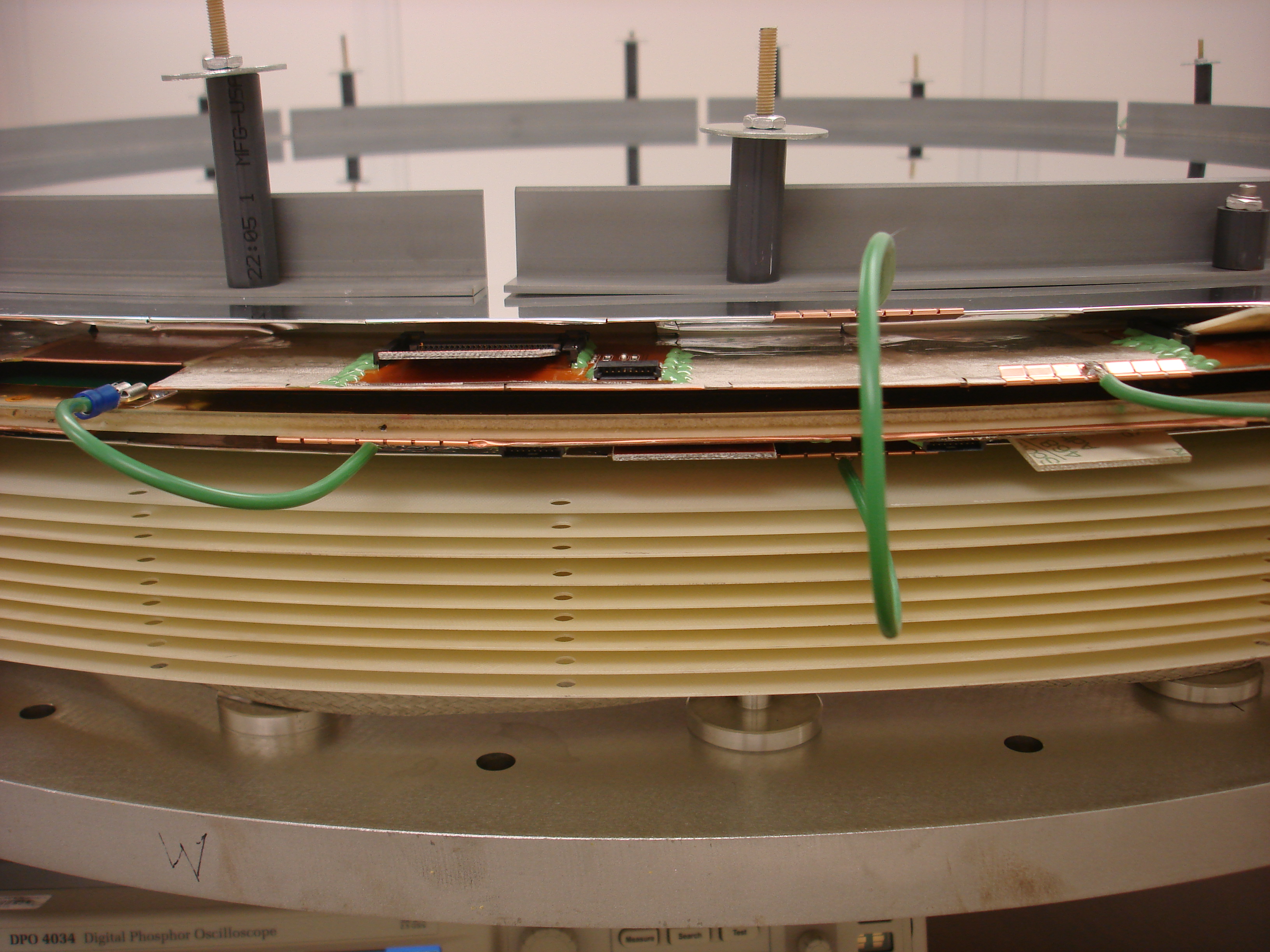
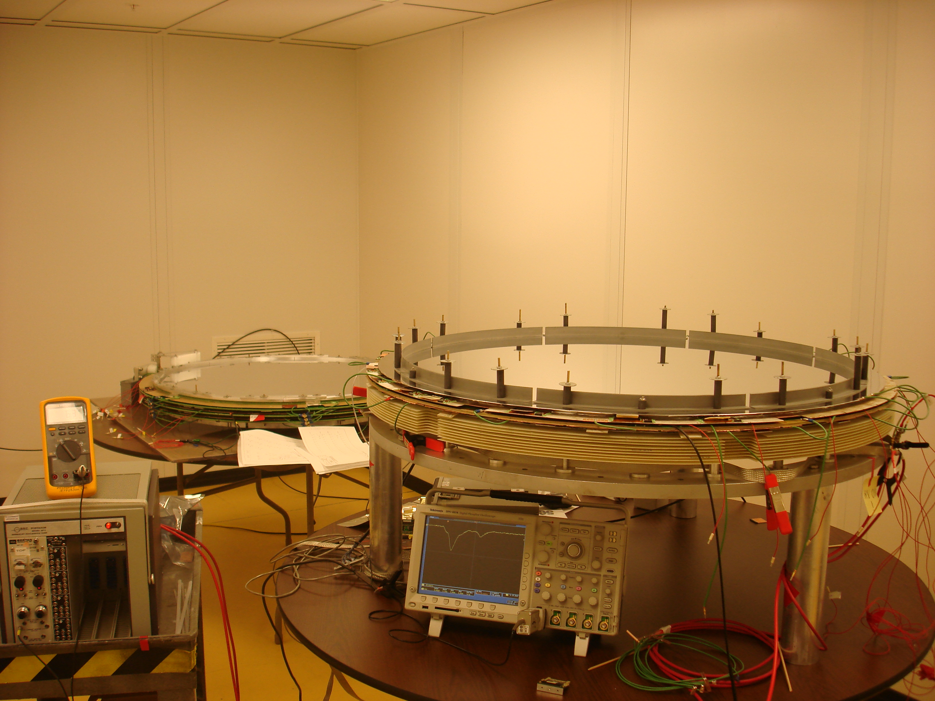
- The pictures linked above, show the configuration of the first chamber package and the testing set-up. After taking the wire frame form the vacuum chamber (vacuum went down to ~6 10^-6 tor) we checked that the frame was no longer conductive and we installed it again in the package. First we had Lexan sheet on the top, than we replaced it with the second cathode and the second end window. The package has no detectable gas leakage and we bubble it with a flow of 20-40 ccpm. On three of the HV sectors (out of four) we were able to apply HV up to 2300V and -500V sense/field with current less than 100 uA. The fourth HV sector shows high current so far: ~500 uA at 2000V/-500V. It may improve, but if not, it will require cleaning. In any case the chamber is operational and we tested all the channels with a scope with differential probe. In the moment we see signals from all the channels (both wires and strips) except one cathode channel on the bottom cathode which connectors are close to a metal pin. We suspect it was damaged when prying the wire frame with a screw driver when it was taken to be put in the vacuum chamber. The pins are very tight (compared to the prototype) and the only way to take a frame out was to rotate the pins while lifting the frame; for that you need to unscrew the hubs from the jig plate. Bill will work on designing pins that are easily removable. Before, there were also another two channels on the top cathode not showing signals but after bending a little the cathode periphery at the daughter card it started working (has to be investigated!). At the beginning of the tests most of the noise was coming from the chamber itself, but later it improved. Generally, the pick-up noise is much lower than on the full-scale prototype. Could be because of the new design cathode shielding, and/or because Blue Crab is less noisy than 126.
- Dave summarized the production progress on the spreadsheet linked above. Techs are working on the second and third cells that will be part of the first package. Remaining for cell#2: tomorrow Chris will put the second phase elements on the wire frame and then we will clean it manually with alcohol. Casey will glue the rigid-flexes. Anatoly is working on the flaps of one of the cathodes and the end windows. Mike and Tina are working on the gas spacer and next cathode foils. On Tuesday we can start assembling the package. Techs were working also on different tooling: Casey made lazy-Susan for attaching the cathodes and gluing rigid-flexes. Al and Caleb are testing/writing software for the new encoder.
Engineering
- Bill, Casey installed the new encoder and it will be used for third wire frame (stringing will start tomorrow). The monuments will be installed on the table later for the fourth chamber.
- Bill is waiting for the quotation of the Al gusset ring (it came at the of the day: ~$1200 per ring; we need 8). We discussed also possible lifting frame and covers for the package. Bill will design coverplates (out of g10) that will be attached to plastic threaded rods. Bill was also working on the procedures.
Electronics
- Tinned or un-tinned flex connectors: all the samples so far, both tinned and un-tinned, show no problems except one channel on the first sample showing connection to ground when you bend it (later it turned out it is a problem of the connector on the daughter board). So, we decided to have them tinned because: (1) the conductive tape gluing works better with tinned, due to the increased thickness of the contacts, and (2) because we can use standard soldering technique, if we have to.
- Chris started receiving signal cables (first CDC type) 75 per week. He will test them at 126 and store them somewhere there.
Chamber testing
- We decided to move the first chamber to the test set-up in EEL126 on Monday. Bill will come on Monday to help with the installation of the holding brackets. Beni and Lubomir will try to find the best way to connect the chamber to the DAQ with the existing electronics in order to maximize the number of the readout channels.