Difference between revisions of "Minutes-6-16-2011"
| Line 25: | Line 25: | ||
== Production == | == Production == | ||
| − | - The pictures linked above, show the configuration of the first chamber package and the testing set-up. After taking the wire frame form the vacuum chamber (vacuum went down to ~6 10^-6 tor) we checked that the frame was no longer conductive and we installed it again in the package. First we had Lexan sheet on the top, than we replaced it with the second cathode and the second end window. The package has no detectable gas leakage and we bubble it with a flow of 20-40 ccpm. On three of the HV sectors (out of four) we were able to apply HV up to 2300V and -500V sense/field with current less than 100 uA. The fourth HV sector shows high current so far: ~500 uA at 2000V/-500V. It may improve, but if not, it will require cleaning. In any case the chamber is operational and we tested all the channels with a scope with differential probe. In the moment we see signals from all the channels (both wires and strips) except one cathode channel on the bottom cathode which connectors are close to a metal pin. We suspect it was damaged when prying the wire frame with a screw driver when it was taken to be put in the vacuum chamber. The pins are very tight (compared to the prototype) and the only way to take a frame out was to rotate the pins while lifting the frame; for that you need to unscrew the hubs from the jig plate. Bill will work on designing pins that are easily removable. At the beginning of the tests the most of the noise was coming from the chamber itself, but later it improved. Generally, the pick-up noise is much lower than on the full-scale prototype. Could be because of the new design cathode shielding, and/or because Blue Crab is less noisy than 126. | + | - The pictures linked above, show the configuration of the first chamber package and the testing set-up. After taking the wire frame form the vacuum chamber (vacuum went down to ~6 10^-6 tor) we checked that the frame was no longer conductive and we installed it again in the package. First we had Lexan sheet on the top, than we replaced it with the second cathode and the second end window. The package has no detectable gas leakage and we bubble it with a flow of 20-40 ccpm. On three of the HV sectors (out of four) we were able to apply HV up to 2300V and -500V sense/field with current less than 100 uA. The fourth HV sector shows high current so far: ~500 uA at 2000V/-500V. It may improve, but if not, it will require cleaning. In any case the chamber is operational and we tested all the channels with a scope with differential probe. In the moment we see signals from all the channels (both wires and strips) except one cathode channel on the bottom cathode which connectors are close to a metal pin. We suspect it was damaged when prying the wire frame with a screw driver when it was taken to be put in the vacuum chamber. The pins are very tight (compared to the prototype) and the only way to take a frame out was to rotate the pins while lifting the frame; for that you need to unscrew the hubs from the jig plate. Bill will work on designing pins that are easily removable. Before, there were also another two channels on the top cathode not showing signals but after bending a little the cathode periphery at the daughter card it started working (has to be investigated!). At the beginning of the tests the most of the noise was coming from the chamber itself, but later it improved. Generally, the pick-up noise is much lower than on the full-scale prototype. Could be because of the new design cathode shielding, and/or because Blue Crab is less noisy than 126. |
| − | - Dave summarized the production progress on the spreadsheet linked above. Techs are working on the second and third cells that will be part of the first package. | + | - Dave summarized the production progress on the spreadsheet linked above. Techs are working on the second and third cells that will be part of the first package. Remaining for cell#2: tomorrow Chris will put the second phase elements on the wire frame and then we will clean it manually with alcohol; Casey will glue the rigid-flexes; Anatoly is working on the flaps of one of the cathodes and the end windows. On Tuesday we can start assembling the package. |
- We are working now on the second chamber set. The second wire frame was strung, glued, positions measured, then the wires were soldered. (After the meeting also the tensions were measured). Tomorrow the wires will be cut and the PCBs populated. Cathodes #3 and #4 are type 3 (as #1 and #2) and ready mechanically. After testing the modified tool we will glue the rigid-flexes. | - We are working now on the second chamber set. The second wire frame was strung, glued, positions measured, then the wires were soldered. (After the meeting also the tensions were measured). Tomorrow the wires will be cut and the PCBs populated. Cathodes #3 and #4 are type 3 (as #1 and #2) and ready mechanically. After testing the modified tool we will glue the rigid-flexes. | ||
Revision as of 18:44, 16 June 2011
June 16, 2011 FDC meeting
Contents
Agenda
- Production Construction Tracking (Dave)
- Engineering (Bill)
- New encoder
- Gusset ring
- Other
- Electronics update (Fernando, Chris)
- Chamber testing at EEL126 (Beni, Lubomir)
- Other
Minutes
Participants: Eugene, Bill, Glenn, Dave, Chris, Beni, Simon, and Lubomir.
Other
At the beginning of the meeting Bill and Dave, representing also other non-physicists, expressed interest in learning more about drift chambers, GlueX detectors and physics and beyond. Eugene, Simon, Beni were happy to answer their questions. We all agreed also to organize a special presentation for them.
Production
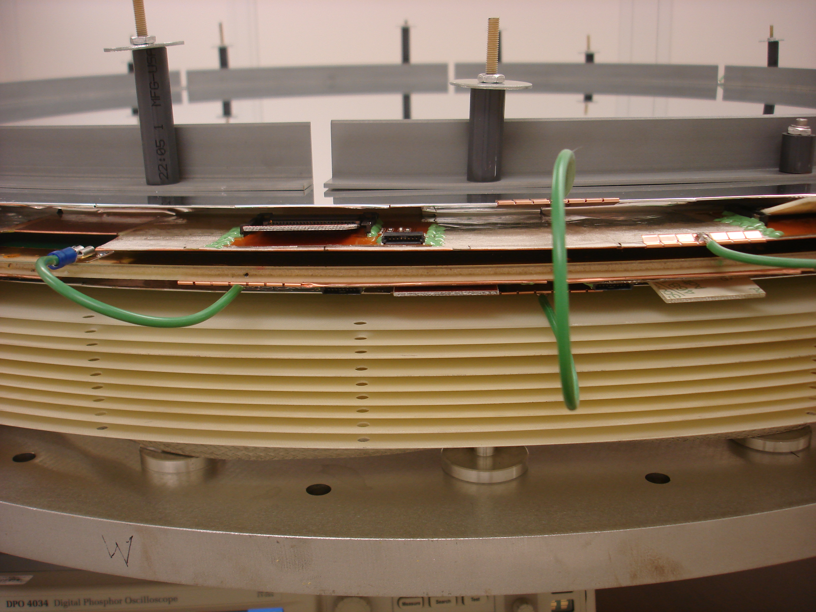
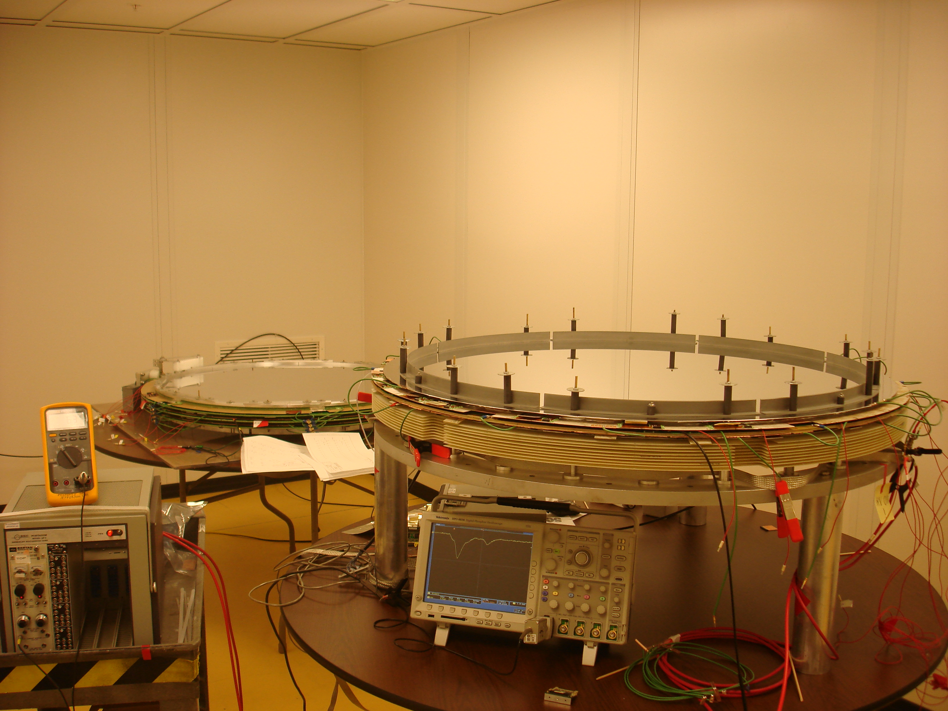
- The pictures linked above, show the configuration of the first chamber package and the testing set-up. After taking the wire frame form the vacuum chamber (vacuum went down to ~6 10^-6 tor) we checked that the frame was no longer conductive and we installed it again in the package. First we had Lexan sheet on the top, than we replaced it with the second cathode and the second end window. The package has no detectable gas leakage and we bubble it with a flow of 20-40 ccpm. On three of the HV sectors (out of four) we were able to apply HV up to 2300V and -500V sense/field with current less than 100 uA. The fourth HV sector shows high current so far: ~500 uA at 2000V/-500V. It may improve, but if not, it will require cleaning. In any case the chamber is operational and we tested all the channels with a scope with differential probe. In the moment we see signals from all the channels (both wires and strips) except one cathode channel on the bottom cathode which connectors are close to a metal pin. We suspect it was damaged when prying the wire frame with a screw driver when it was taken to be put in the vacuum chamber. The pins are very tight (compared to the prototype) and the only way to take a frame out was to rotate the pins while lifting the frame; for that you need to unscrew the hubs from the jig plate. Bill will work on designing pins that are easily removable. Before, there were also another two channels on the top cathode not showing signals but after bending a little the cathode periphery at the daughter card it started working (has to be investigated!). At the beginning of the tests the most of the noise was coming from the chamber itself, but later it improved. Generally, the pick-up noise is much lower than on the full-scale prototype. Could be because of the new design cathode shielding, and/or because Blue Crab is less noisy than 126.
- Dave summarized the production progress on the spreadsheet linked above. Techs are working on the second and third cells that will be part of the first package. Remaining for cell#2: tomorrow Chris will put the second phase elements on the wire frame and then we will clean it manually with alcohol; Casey will glue the rigid-flexes; Anatoly is working on the flaps of one of the cathodes and the end windows. On Tuesday we can start assembling the package.
- We are working now on the second chamber set. The second wire frame was strung, glued, positions measured, then the wires were soldered. (After the meeting also the tensions were measured). Tomorrow the wires will be cut and the PCBs populated. Cathodes #3 and #4 are type 3 (as #1 and #2) and ready mechanically. After testing the modified tool we will glue the rigid-flexes.
- Starting the beginning of this week, the AC of the bay area was set to higher temperature (85 F) only over the night. Ron Bartek monitors the work of the clean room AC (settings unchanged). Eugene was concerned also about the procedures and materials that are outside of the clean room. So far the humidity there was not so high (45%) but we should monitor it constantly. To be on the safe side we decided to bring all wire frames inside the clean room to prevent the absorption of moisture in the Rohacell
Engineering
- We decided not to use ultrasonic cleaning for the second wire frame. If the vacuuming will work to take out the moisture from the first chamber we may try to use the ultrasonic cleaning for the third chamber, but making sure all the holes are reliably sealed. In fact before the first production chamber, we put a testing frame (old design) in the ultrasonic bath and this frame doesn't show measurable conductivity through the Rohacell; most likely it was sealed better.
- Rigid-flex pressing tool: it's back from the machine shop and today Casey will check the flatness. The shoe was narrowed down to 4.5mm.
- Bill is designing the end gussets that hold the package together. His proposal is to make one piece out of aluminum angle (1x1' 2mm thick). We discussed also the possibility to use Be. Eugene: it will be very expensive (1m diameter) because it's toxic when machined, but it has factor of 4 bigger radiation length. Simon will add the Al ring in the simulation to investigate the effects on the calorimeter photon registration efficiency.
Electronics
- Chris made the new testing card with LEDs on the top; still need a cable to use it.
- There was confusion when populating the PCBs: the bill of materials was in contradiction with the schematics. We populated the boards according the the bill, but it turned out the schematics is the correct one. The HV PCBs were corrected (but as it turned out we had bigger problems with the HV), so later we will correct the signal side as well. Kim created a new version of the material list and Fernando will create a traveler with the correct documentation.
Chamber testing
- Caleb started working on the position measurement problem. His plan is to create software (Visual Basic) to track down the problem and also to improve the procedure.
- The position measurements for the second wire frame showed sigma of ~25 microns. Few of the wires exceeded 100 even 200 microns offsets but were corrected by re-taping the wires. This is the first wire frame after the pin rail was fixed: now it doesn't show the step in the middle but some kink (change in the slope) is visible. Maybe due to the use of the stepper motor. After finishing the second wire frame Bill install the new encoder and hopefully this will fix the problem.
-->