Difference between revisions of "Minutes-4-11-2013"
From GlueXWiki
| Line 24: | Line 24: | ||
- Dave for the spare package: Two wire planes (#2 and #3) have been deadened, two more remaining. The filed wire on #2 was fixed (broke during deadening). It turned out we don't have enough HV cables (short cables with male connectors) that are soldered on the wired frames, and we have order them. This is because we originally planned for 4 spare cells. | - Dave for the spare package: Two wire planes (#2 and #3) have been deadened, two more remaining. The filed wire on #2 was fixed (broke during deadening). It turned out we don't have enough HV cables (short cables with male connectors) that are soldered on the wired frames, and we have order them. This is because we originally planned for 4 spare cells. | ||
| − | - Package #3 repair: the three field wires on the wire frame of cell #6 were fixed and on Monday we | + | - Package #3 repair: the three field wires on the wire frame of cell #6 were fixed and on Monday we installed the sixth cell on the package upside-down. We ended up holding the spacer ring with fingers (taping to polyethylene didn't work) when installing it together with the wire frame, but it was successful: no gas leakage was found. Since Monday we are flushing the package with gas, oxygen went down to 700ppm and today we applied 2000V/-500V so far without problems. We will continue testing it till Monday, but already tomorrow we can start replacing the cooling tubes - they have to be positioned in a different way as for the other packages. Next week we plan to finish also with the grounding connections, HV connections and with the installation of the manifolds. Then we will move it (during the week of 22-26 of April) to 126 for testing with the full electronics. Fernando: by that time we will have 30 fADC125 ready to be used (3 will go to CMU). |
== Installation == | == Installation == | ||
| − | - | + | - The channel assignment schemes are attached above. Fernando explained how to use the first one, the channels/cables are ordered according the their rack, crate, slot numbers. The other two files (Vlad's) represent the view from the detector side, separately for the signal and LV cables. The cables are ordered in increasing azimuthal angle, started from the top counterclockwise when looking from the upstream side. |
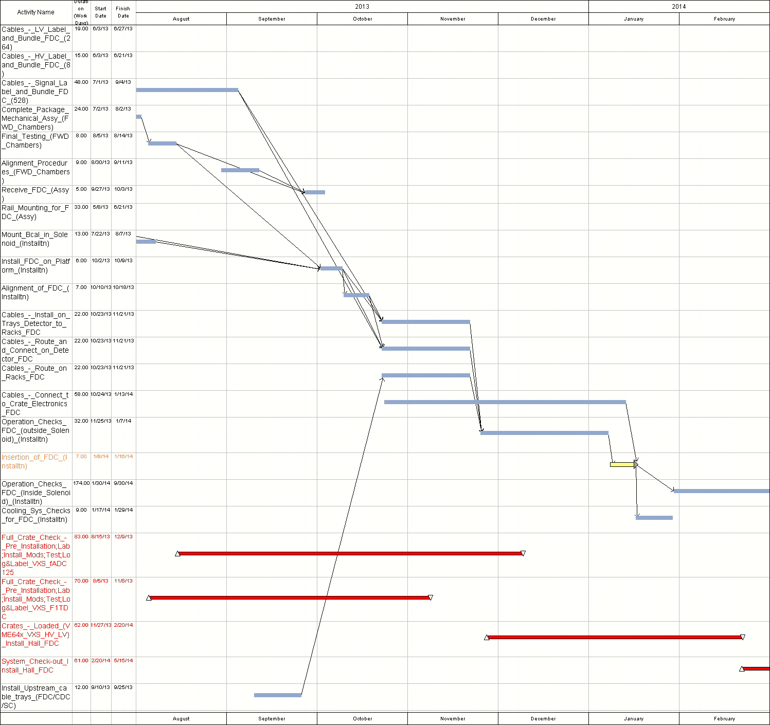
| − | - | + | - The schedule for the FDC installation and related activities (linked above) was updated from the recent version 3 of the rebaselined schedule. There are important changes related to the electronics: the installation of the fADC125s in the racks is postponed by ~8 weeks, starts Nov 23. If this is the case, the FDC installation has to be postponed as well. Eugene: this was done because of the manpower spike for this period of time. |
| − | + | ||
| − | + | ||
- We discussed possible practicing at Blue Crab with the following configuration. We will use two installation carts, going downstream, one for one half of the mesh cylinder, and the other for one FDC package and the mock-up. The idea is to prototype one quadrant of the signal cables (132). The cables for that quadrant will come from the FDC package and the rest will be attached to the mock-up representing the other three packages. The cables will be attached up to the end of the mesh running between the rails. We have all the major parts to do this. The bearings on the mesh have to be installed. Will move also 132 signal cables from 117 to Blue Crab. | - We discussed possible practicing at Blue Crab with the following configuration. We will use two installation carts, going downstream, one for one half of the mesh cylinder, and the other for one FDC package and the mock-up. The idea is to prototype one quadrant of the signal cables (132). The cables for that quadrant will come from the FDC package and the rest will be attached to the mock-up representing the other three packages. The cables will be attached up to the end of the mesh running between the rails. We have all the major parts to do this. The bearings on the mesh have to be installed. Will move also 132 signal cables from 117 to Blue Crab. | ||
Revision as of 16:59, 11 April 2013
April 11, 2013 FDC meeting
Agenda
- Production Construction Tracking (Dave)
- Package #3 repair
- Installation (Lubomir, Bill)
- Channel assignment: rack's side (Fernando), signal cables detector side (Vlad's scheme), LV cables detector side (Vlad's scheme)
- Schedule latest version
- Plans for practicing at Blue Crab
- Engineering (Bill)
- Cooling system tests
- Electronics (Chris, Nick)
- Tests at EEL126 FDC E-log (Beni)
- Other