Difference between revisions of "Minutes-2-9-2012"
(Created page with "February 9, 2012 FDC meeting = Agenda = # Production update [http://www.jlab.org/Hall-D/detector/fdc/production/FDC_Construction_February_9_2012.xlsx Construction Tracking] (D...") |
m (Text replacement - "/halldweb1.jlab.org/" to "/halldweb.jlab.org/") |
||
| (11 intermediate revisions by one other user not shown) | |||
| Line 6: | Line 6: | ||
#* Third package status | #* Third package status | ||
#* Electroplating results | #* Electroplating results | ||
| − | # First package testing (Beni, Lubomir) | + | # First package testing [https://halldweb.jlab.org/elog-halld/FDC/ FDC ELOG] (Beni, Lubomir) |
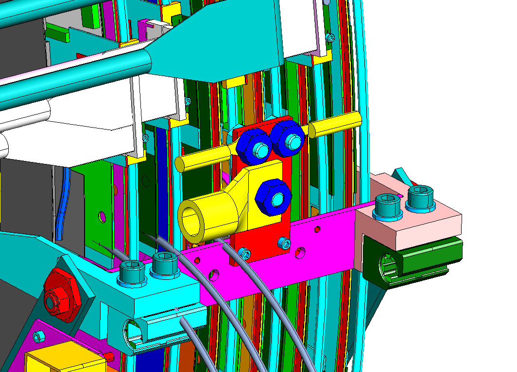
| − | # Engineering update (Bill) | + | # Engineering update [http://www.jlab.org/Hall-D/detector/fdc/drawings/grounding_plate.png grounding plate] (Bill) |
# Electronics update (Chris) | # Electronics update (Chris) | ||
# Other | # Other | ||
| − | |||
= Minutes = | = Minutes = | ||
| − | Participants: Bill, Dave | + | Participants: Bill, Dave, Chris, Mark, Simon, Beni, and Lubomir. |
== Production == | == Production == | ||
| − | - Dave: wire boards #20 and #21 | + | - Dave: wire boards #20 and #21 waiting for electroplating. #22 will be populated soon by Chris. Dave showed pictures how the problem on #23 was fixed: |
| + | the signal trace on wire #96 had short to ground on the back side of the PCB close to the via. The frame was drilled on the back side through the G10 and Rohacell to reach the board, the trace was disconnected before the via and insulated wire was used to make connection to the other side of the board through the via. Wire frame #13 was given to the EEFAB people for gluing the traces under the HV caps that de-laminated, but they have sent the board to an outside company. There they decided that the traces have enough strength and soldered the HV caps, all this without our knowledge! Fortunately, after replacing one cap with a solder ball on the back, the dark current is now low enough. The next step was to put epoxy on the caps since they are hanging now on the traces. For that, samples were made to test the dark current change. On one cap we had ~200nA with Scotch-weld and ~400nA with Epon one day after gluing across the cap. Therefor the decision was to put Scotch-weld only on the sides of the caps. Ten caps on the sides of the wire frame were already glued. After making sure the dark current is reasonable we will continue with the rest. Working also the cathodes for the third cell of the third package. | ||
| − | - | + | - Two more electroplating samples were made. One with the original procedure with extra polishing; before using the same procedure all the wires were fine except one. Second sample with increasing the time instead of the current compared to the 6cm-diameter original procedure, and in addition the polishing current was increased to have a ratio of 3 w.r.t electroplating current. Will be waiting for the microscope pictures from Olga to make a decision. |
| − | + | ||
| − | + | ||
== First package testing == | == First package testing == | ||
| − | |||
| − | |||
| − | - Beni | + | - Beni showed results posted in the new FDC Elog linked above, entries #9-13. The wires of the top four planes are connected to the electronics. All channels are working fine now, except one noisy. To reduce the noise we had to increase the threshold to 20V on the supply (Vth=2.0V, or ~40mV effective threshold after the amplifier) which is close to the maximum possible value for the pre-amp of 25V! Beni made a code to estimate the chamber efficiencies using IU chamber tracks projecting them on the FDC cells and looking for at least one wire firing on the corresponding cell. One can see (entry #11) one side of all the cells having higher efficiencies, most likely correlated with the gas input. Using signals from particular wires Beni estimated the FDC wire orientation w.r.t. external tracking system and in between the cells (#13). |
| − | - | + | - Lubomir: good start for the first package, all wires working, no HV trips below 2150V with 50/50 Ar/CO2, while two channels tripped at 2200V which corresponds to a high gain of >10^5. Changing the HV from 2100/-500V to 2200/-500V (entry #12) improved the efficiency significantly. Now testing 21500/-500V. On the other hand we should try different ways to reduce the noise. One is to improve the LV distribution that contributes now to the noise problem due to voltage drops over the cables. After the meeting Beni installed new LV cables from Chris, one per plane, and the noise was reduced so that we have now 15V threshold. |
| − | + | ||
== Engineering == | == Engineering == | ||
| − | - Bill | + | - Bill discussed with Beni the gas system already before the meeting. With the present MKS we can't have flows higher than 280-300 ccpm and we may need higher flows to improve the chamber efficiency. Bill will start designing the new gas system. At present Beni has two mass flow controllers with 500 ccpm max flow (for nitrogen) capable of supplying in total >700 ccpm Ar/CO2. |
| − | - | + | - Bill asked what is needed to improve the grounding (see drawing of the grounding connections to the package attached above). The idea is to have six grounding places around the chamber where all the cathodes, wire frames, end windows, cooling tubes are connected together. Then we will have an external ground coming to the grounding plate shown on the drawing that has connections also for the HV return. The current idea is to use the tubes to connect the external ground to these six places. For that Bill will design a Cu clamp instead just the plate shown on the drawing. For the connections to the tubes at the six grounding places Bill suggested soldering terminals to the tubes. |
| + | - What if we have to disassemble the cooling tubes: the way the cooling system is designed, because of the the bending of the tubes, Bill thinks that we have to cut the tubes and then make new ones. | ||
| + | |||
== Electronics == | == Electronics == | ||
| − | - Chris | + | - Chris proposed LV cables that we have now with two LV connectors at one end to be used for the tests of the first package, by directly connecting the wires at the other end to the LV supply. |
| + | |||
| + | - Most of the pre-amp cards for the FDC are assembled and are/will be tested by Cody. | ||
== Other == | == Other == | ||
| − | - | + | - Simon made changes in the TDR, separating the gas considerations from the introduction |
| − | - | + | - No FDC meeting next week, due to the collaboration meeting. |
Latest revision as of 06:29, 1 April 2015
February 9, 2012 FDC meeting
Contents
Agenda
- Production update Construction Tracking (Dave)
- Third package status
- Electroplating results
- First package testing FDC ELOG (Beni, Lubomir)
- Engineering update grounding plate (Bill)
- Electronics update (Chris)
- Other
Minutes
Participants: Bill, Dave, Chris, Mark, Simon, Beni, and Lubomir.
Production
- Dave: wire boards #20 and #21 waiting for electroplating. #22 will be populated soon by Chris. Dave showed pictures how the problem on #23 was fixed: the signal trace on wire #96 had short to ground on the back side of the PCB close to the via. The frame was drilled on the back side through the G10 and Rohacell to reach the board, the trace was disconnected before the via and insulated wire was used to make connection to the other side of the board through the via. Wire frame #13 was given to the EEFAB people for gluing the traces under the HV caps that de-laminated, but they have sent the board to an outside company. There they decided that the traces have enough strength and soldered the HV caps, all this without our knowledge! Fortunately, after replacing one cap with a solder ball on the back, the dark current is now low enough. The next step was to put epoxy on the caps since they are hanging now on the traces. For that, samples were made to test the dark current change. On one cap we had ~200nA with Scotch-weld and ~400nA with Epon one day after gluing across the cap. Therefor the decision was to put Scotch-weld only on the sides of the caps. Ten caps on the sides of the wire frame were already glued. After making sure the dark current is reasonable we will continue with the rest. Working also the cathodes for the third cell of the third package.
- Two more electroplating samples were made. One with the original procedure with extra polishing; before using the same procedure all the wires were fine except one. Second sample with increasing the time instead of the current compared to the 6cm-diameter original procedure, and in addition the polishing current was increased to have a ratio of 3 w.r.t electroplating current. Will be waiting for the microscope pictures from Olga to make a decision.
First package testing
- Beni showed results posted in the new FDC Elog linked above, entries #9-13. The wires of the top four planes are connected to the electronics. All channels are working fine now, except one noisy. To reduce the noise we had to increase the threshold to 20V on the supply (Vth=2.0V, or ~40mV effective threshold after the amplifier) which is close to the maximum possible value for the pre-amp of 25V! Beni made a code to estimate the chamber efficiencies using IU chamber tracks projecting them on the FDC cells and looking for at least one wire firing on the corresponding cell. One can see (entry #11) one side of all the cells having higher efficiencies, most likely correlated with the gas input. Using signals from particular wires Beni estimated the FDC wire orientation w.r.t. external tracking system and in between the cells (#13).
- Lubomir: good start for the first package, all wires working, no HV trips below 2150V with 50/50 Ar/CO2, while two channels tripped at 2200V which corresponds to a high gain of >10^5. Changing the HV from 2100/-500V to 2200/-500V (entry #12) improved the efficiency significantly. Now testing 21500/-500V. On the other hand we should try different ways to reduce the noise. One is to improve the LV distribution that contributes now to the noise problem due to voltage drops over the cables. After the meeting Beni installed new LV cables from Chris, one per plane, and the noise was reduced so that we have now 15V threshold.
Engineering
- Bill discussed with Beni the gas system already before the meeting. With the present MKS we can't have flows higher than 280-300 ccpm and we may need higher flows to improve the chamber efficiency. Bill will start designing the new gas system. At present Beni has two mass flow controllers with 500 ccpm max flow (for nitrogen) capable of supplying in total >700 ccpm Ar/CO2.
- Bill asked what is needed to improve the grounding (see drawing of the grounding connections to the package attached above). The idea is to have six grounding places around the chamber where all the cathodes, wire frames, end windows, cooling tubes are connected together. Then we will have an external ground coming to the grounding plate shown on the drawing that has connections also for the HV return. The current idea is to use the tubes to connect the external ground to these six places. For that Bill will design a Cu clamp instead just the plate shown on the drawing. For the connections to the tubes at the six grounding places Bill suggested soldering terminals to the tubes.
- What if we have to disassemble the cooling tubes: the way the cooling system is designed, because of the the bending of the tubes, Bill thinks that we have to cut the tubes and then make new ones.
Electronics
- Chris proposed LV cables that we have now with two LV connectors at one end to be used for the tests of the first package, by directly connecting the wires at the other end to the LV supply.
- Most of the pre-amp cards for the FDC are assembled and are/will be tested by Cody.
Other
- Simon made changes in the TDR, separating the gas considerations from the introduction
- No FDC meeting next week, due to the collaboration meeting.