Difference between revisions of "Minutes-2-2-2012"
(→Electronics) |
|||
| (11 intermediate revisions by the same user not shown) | |||
| Line 1: | Line 1: | ||
| − | + | February 2, 2012 FDC meeting | |
= Agenda = | = Agenda = | ||
| Line 10: | Line 10: | ||
# Engineering update (Bill) | # Engineering update (Bill) | ||
#* Cooling system | #* Cooling system | ||
| − | #* [http://www.jlab.org/Hall-D/detector/fdc/drawings/GAP_TO_CONNECTOR.png HV connector position] | + | #* Other: [http://www.jlab.org/Hall-D/detector/fdc/drawings/GAP_TO_CONNECTOR.png HV connector position] |
# Electronics update (Chris) | # Electronics update (Chris) | ||
| − | # Other | + | # Other: once more [http://www.jlab.org/Hall-D/detector/fdc//tracking/FDC_NamingConvention.docx naming convention] |
| − | + | ||
| − | + | ||
= Minutes = | = Minutes = | ||
| − | Participants: Bill, Dave, Chris, | + | Participants: Bill, Dave, Beni, Chris, Simon, Mark, Eugene, and Lubomir. |
== Production == | == Production == | ||
| − | - Dave: wire | + | - Dave: wire boards #20 and #21 ready waiting just for electroplating. #22 ready for tension measurements. Problem found on #23 (before stringing!): a signal trace (#96) has short to ground most likely in the via or on the trace on the back side of the board. The plan is first to drill the via and confirm the problem is there. Then we will make an opening in the frame to access the trace on the back side of the board, fortunately there's Rohacell on the back of the via, not solid G10. Then we will solder insulated wire to make the connection. Cathode #33 was glued to the frame with some offset of ~3mm at most. One frame hole covers a trace on the connector; it can be fixed in principal but also the offset is not acceptable (Simon). So we have enough spare material to replace this cathode and will use it only if needed. Wire frame #13 (with the capacitor traces de-laminated) was inspected by EEFAB people. They said it can be fixed in two days, however later they claimed they need a $26K machine for that and want to share the costs; Dave will negotiate with them. |
| − | - | + | - Another sample using the original electroplating recipe was made with the hope the surface will be smoother. Waiting for the microscope pictures from Olga to make a decision whether we can continue with the wire deadening: two wire planes ready and waiting for this decision. |
| − | = First package testing | + | - Second package was put in the rail frame. We discussed that one of the bearings must be fixed (no gap), right now both are loose, so has to be replaced later. Chris: pre-amps for four cells ready but ran out of screws then Cody has to test them. After that we will install them on the package together with the cooling tubes. |
| + | |||
| + | == First package testing == | ||
| − | - | + | - The problems we had before with the HV were understood and fixed after swapping the Ar and CO2 in the gas system. Right now we have Ar/CO2 50/50 and all the channels up at +1920/-500V operating without trips already 24 hours. The gain, as roughly estimated with a source, is ~10^4 and the package is ready for the tests. Normally we work at 4-8 10^4, so later we will increase the HV by 100-150V. |
| − | - | + | - Beni pointed out that three of the HV channels (one + and two -) trip at 1V even after they have been disconnected from the chamber. Problem might be at the cable/connectors or in the module. After the meeting Beni found that the problem is in the CAEN modules: not only that the current resolution is very poor to be used with chambers, but there's internal problem with the way the current limitation works at low thresholds. He found that many channels (on four A1535 modules) need initial increase of the current limits up to 100uA to get them working, eventually one could decrease the limits back to 2-5 uA. |
| − | - | + | - Gas problem: the gas tightness is worse than it was at Blue Crab. Now the flow rate is 280ccpm and pressure inside ~40Pa. Most likely there's leakage at the gas inlets that has to be fixed later. Bill: for the next packages we should be more careful handling the tubes connected to the inlets. |
| − | + | ||
| − | + | ||
| − | + | ||
| − | + | ||
| − | + | ||
| − | + | ||
== Engineering == | == Engineering == | ||
| − | - | + | - Bill: will come with a plan to test the pump for the gas system; many-fold designed and now in production. |
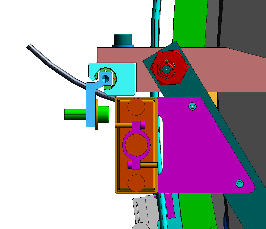
| − | - | + | - There's enough clearance between the HV connector and the rail. If we need we can move the connector slightly inside. Bill proposed to mount the copper grounding plate on the side of the holding brackets that is perpendicular to the chamber plane. |
| − | + | ||
== Electronics == | == Electronics == | ||
| − | - Chris | + | - Chris and Nick are working on the pre-amp assembly. Chris gave details about the grounding lugs to be used on the copper plate. There was no answer at the meeting whether we will have one thick grounding cable per package or two, one per side? |
| + | |||
| + | == Other == | ||
| − | -- | + | - We decided to keep the old naming/numbering convention, even if it creates confusion of the channel numbering on the pre-amps. |
Latest revision as of 19:53, 2 February 2012
February 2, 2012 FDC meeting
Contents
Agenda
- Production update Construction Tracking (Dave)
- Third package status
- Electroplating results
- Plans for the second package
- First package testing (Lubomir, Beni)
- Engineering update (Bill)
- Cooling system
- Other: HV connector position
- Electronics update (Chris)
- Other: once more naming convention
Minutes
Participants: Bill, Dave, Beni, Chris, Simon, Mark, Eugene, and Lubomir.
Production
- Dave: wire boards #20 and #21 ready waiting just for electroplating. #22 ready for tension measurements. Problem found on #23 (before stringing!): a signal trace (#96) has short to ground most likely in the via or on the trace on the back side of the board. The plan is first to drill the via and confirm the problem is there. Then we will make an opening in the frame to access the trace on the back side of the board, fortunately there's Rohacell on the back of the via, not solid G10. Then we will solder insulated wire to make the connection. Cathode #33 was glued to the frame with some offset of ~3mm at most. One frame hole covers a trace on the connector; it can be fixed in principal but also the offset is not acceptable (Simon). So we have enough spare material to replace this cathode and will use it only if needed. Wire frame #13 (with the capacitor traces de-laminated) was inspected by EEFAB people. They said it can be fixed in two days, however later they claimed they need a $26K machine for that and want to share the costs; Dave will negotiate with them.
- Another sample using the original electroplating recipe was made with the hope the surface will be smoother. Waiting for the microscope pictures from Olga to make a decision whether we can continue with the wire deadening: two wire planes ready and waiting for this decision.
- Second package was put in the rail frame. We discussed that one of the bearings must be fixed (no gap), right now both are loose, so has to be replaced later. Chris: pre-amps for four cells ready but ran out of screws then Cody has to test them. After that we will install them on the package together with the cooling tubes.
First package testing
- The problems we had before with the HV were understood and fixed after swapping the Ar and CO2 in the gas system. Right now we have Ar/CO2 50/50 and all the channels up at +1920/-500V operating without trips already 24 hours. The gain, as roughly estimated with a source, is ~10^4 and the package is ready for the tests. Normally we work at 4-8 10^4, so later we will increase the HV by 100-150V.
- Beni pointed out that three of the HV channels (one + and two -) trip at 1V even after they have been disconnected from the chamber. Problem might be at the cable/connectors or in the module. After the meeting Beni found that the problem is in the CAEN modules: not only that the current resolution is very poor to be used with chambers, but there's internal problem with the way the current limitation works at low thresholds. He found that many channels (on four A1535 modules) need initial increase of the current limits up to 100uA to get them working, eventually one could decrease the limits back to 2-5 uA.
- Gas problem: the gas tightness is worse than it was at Blue Crab. Now the flow rate is 280ccpm and pressure inside ~40Pa. Most likely there's leakage at the gas inlets that has to be fixed later. Bill: for the next packages we should be more careful handling the tubes connected to the inlets.
Engineering
- Bill: will come with a plan to test the pump for the gas system; many-fold designed and now in production.
- There's enough clearance between the HV connector and the rail. If we need we can move the connector slightly inside. Bill proposed to mount the copper grounding plate on the side of the holding brackets that is perpendicular to the chamber plane.
Electronics
- Chris and Nick are working on the pre-amp assembly. Chris gave details about the grounding lugs to be used on the copper plate. There was no answer at the meeting whether we will have one thick grounding cable per package or two, one per side?
Other
- We decided to keep the old naming/numbering convention, even if it creates confusion of the channel numbering on the pre-amps.