Difference between revisions of "Minutes-11-12-2015"
(→Electronics) |
|||
| (8 intermediate revisions by the same user not shown) | |||
| Line 16: | Line 16: | ||
#* Response Function with scope [http://www.jlab.org/Hall-D/detector/fdc/electronics/tekResFunOK.png 300mV], [http://www.jlab.org/Hall-D/detector/fdc/electronics/tekResFunSaturation.png 600mV] | #* Response Function with scope [http://www.jlab.org/Hall-D/detector/fdc/electronics/tekResFunOK.png 300mV], [http://www.jlab.org/Hall-D/detector/fdc/electronics/tekResFunSaturation.png 600mV] | ||
#* Response Function with fADC125: [http://www.jlab.org/Hall-D/detector/fdc/electronics/RF_CDC_300mV.pdf 300mV], [http://www.jlab.org/Hall-D/detector/fdc/electronics/RF_CDC_600mV.pdf 600mV], [http://www.jlab.org/Hall-D/detector/fdc/electronics/RFmaxmin.pdf summary plot] | #* Response Function with fADC125: [http://www.jlab.org/Hall-D/detector/fdc/electronics/RF_CDC_300mV.pdf 300mV], [http://www.jlab.org/Hall-D/detector/fdc/electronics/RF_CDC_600mV.pdf 600mV], [http://www.jlab.org/Hall-D/detector/fdc/electronics/RFmaxmin.pdf summary plot] | ||
| + | #* [https://halldweb1.jlab.org/wiki/index.php/CDC_transfer_func_attempt Naomi's studies of response function] | ||
# Engineering (Dave) | # Engineering (Dave) | ||
# Other | # Other | ||
| − | |||
| − | |||
| − | |||
= Minutes = | = Minutes = | ||
| Line 28: | Line 26: | ||
== CDC update == | == CDC update == | ||
| − | - Mike | + | - Mike showed presentation (attached) about precise fitting of the time-to-distance in presence of tube deformation. The 3D plots show the average drift distance (from track fitting) as function of drift time and wire offset from the center. The Garfield results don't describe the data very well, but using the same functional form they were fitted to the data. The time-to-distance relation obtained in this way turned out to be different for different runs (not clear why). As a result of this procedure the resolution looks very good (last slide). |
| + | Once Mike has the correct relation he plans to run the alignment procedure once more. | ||
| − | - | + | - Plan to run DAQ with both CDC and FDC over the weekend. Cody made some fixes in the firmware. |
== FDC update == | == FDC update == | ||
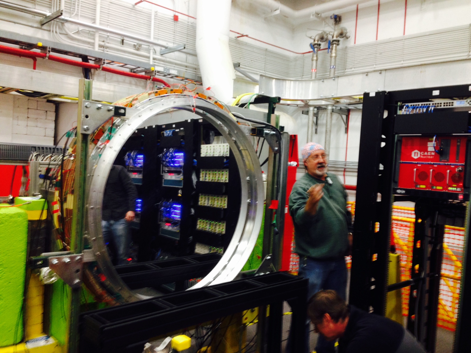
| − | - | + | - On Wednesday the spare package has been moved to the Hall (picture). Signal and LV cables have been connected. We will use the right side of the ST crate - the setting of the TI needs to be changed. HV connections and grounding will be done soon. The middle of the package is above the beam line, thus making space around it. There will be also no need to remove it when backing the target and working on the CDC. Curtis mentioned the need to protect the package at the downstream side - after the meeting aluminum cover was installed there. |
| − | + | ||
| − | - | + | |
| − | + | ||
| − | + | ||
== Electronics == | == Electronics == | ||
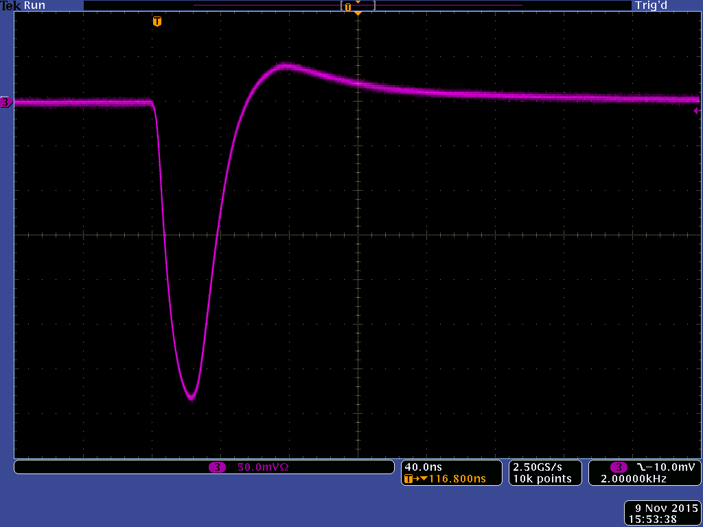
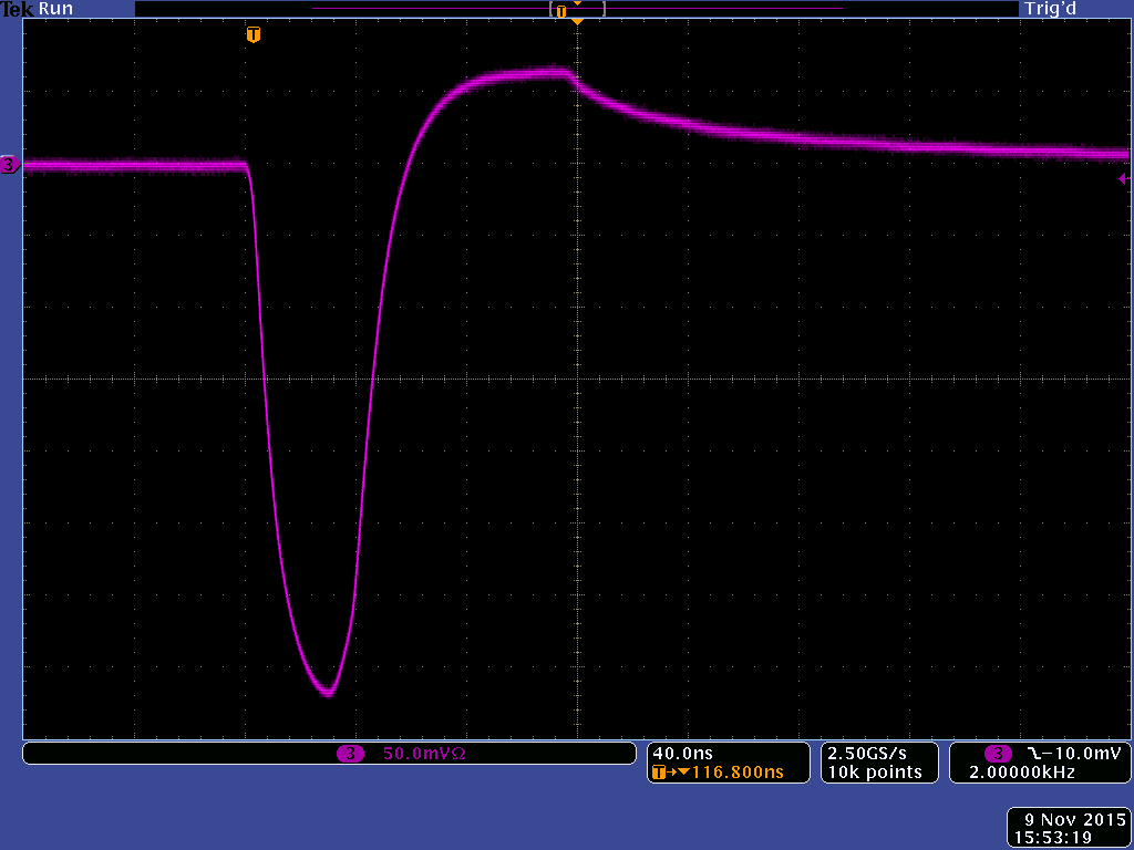
| − | - | + | - Lubomir and Luke measured the response function of the FDC preamp-cable-fADC125 system using the DAQ in the tagger. We used a charge injector at the input - step function from pulse generator on 1pC capacitor on a board that Fernando used before. All the millivolts in the above plots correspond to the step amplitude. We first looked with a scope and found that the peak and tail-cancellation parts saturate in different way (first two plots) - Fernando says that's normal. |
| − | + | ||
| − | + | ||
| − | + | ||
| − | + | ||
| − | + | ||
| − | - | + | |
| − | + | ||
| − | + | ||
| − | + | ||
| − | + | ||
| − | -- | + | - The last plot shows summary of the measurements with fADC125: the max (red) and min (blue, absolute value) of the response function for different input charges. The range with good linearity of the max is narrower that that range for the tail-cancellation part (the minimum). Thus, the poor dE/dx resolution of the FDC can be explained by saturation effects present already at ~2000 units, i.e. half of the fADC125 range. The undershooting is about 20-25% of the peak amplitude. Looking and the Naomi's result for the CDC pre-amp we see that there the tail-cancellation is only about 10%. This might be an explanation for the ion tails seen in the CDC. We will repeat the measurement with a CDC pre-amp. |
Latest revision as of 19:04, 12 November 2015
November 12, 2015 Drift Chamber meeting
Connection
- Instructions for Bluejeans meeting connection
- Meeting ID: 290664653
- To join via a Web Browser, go to the page [1] https://bluejeans.com/290664653.
Agenda
- CDC update (Mike, Simon)
- FDC update (Lubomir, Luke)
- Electronics (Fernando, Chris, Nick)
- Response Function with scope 300mV, 600mV
- Response Function with fADC125: 300mV, 600mV, summary plot
- Naomi's studies of response function
- Engineering (Dave)
- Other
Minutes
Participants: Curtis, Naomi, Mike (CMU), Sean (NU), Fernando, Cody, Luke, Dave, Chris, Nick, Simon, Beni, and Lubomir (JLab).
CDC update
- Mike showed presentation (attached) about precise fitting of the time-to-distance in presence of tube deformation. The 3D plots show the average drift distance (from track fitting) as function of drift time and wire offset from the center. The Garfield results don't describe the data very well, but using the same functional form they were fitted to the data. The time-to-distance relation obtained in this way turned out to be different for different runs (not clear why). As a result of this procedure the resolution looks very good (last slide). Once Mike has the correct relation he plans to run the alignment procedure once more.
- Plan to run DAQ with both CDC and FDC over the weekend. Cody made some fixes in the firmware.
FDC update
- On Wednesday the spare package has been moved to the Hall (picture). Signal and LV cables have been connected. We will use the right side of the ST crate - the setting of the TI needs to be changed. HV connections and grounding will be done soon. The middle of the package is above the beam line, thus making space around it. There will be also no need to remove it when backing the target and working on the CDC. Curtis mentioned the need to protect the package at the downstream side - after the meeting aluminum cover was installed there.
Electronics
- Lubomir and Luke measured the response function of the FDC preamp-cable-fADC125 system using the DAQ in the tagger. We used a charge injector at the input - step function from pulse generator on 1pC capacitor on a board that Fernando used before. All the millivolts in the above plots correspond to the step amplitude. We first looked with a scope and found that the peak and tail-cancellation parts saturate in different way (first two plots) - Fernando says that's normal.
- The last plot shows summary of the measurements with fADC125: the max (red) and min (blue, absolute value) of the response function for different input charges. The range with good linearity of the max is narrower that that range for the tail-cancellation part (the minimum). Thus, the poor dE/dx resolution of the FDC can be explained by saturation effects present already at ~2000 units, i.e. half of the fADC125 range. The undershooting is about 20-25% of the peak amplitude. Looking and the Naomi's result for the CDC pre-amp we see that there the tail-cancellation is only about 10%. This might be an explanation for the ion tails seen in the CDC. We will repeat the measurement with a CDC pre-amp.