Difference between revisions of "Minutes-1-19-2012"
| Line 12: | Line 12: | ||
# Testing in 126 (Beni) | # Testing in 126 (Beni) | ||
# Other | # Other | ||
| − | |||
| − | |||
= Minutes = | = Minutes = | ||
| Line 23: | Line 21: | ||
- Dave: working on the first cell of the third package. Wire frame was strung, but two field wires (next to each other) showed lower tension (106g instead of 130g nominal, but actually mean measured value is around 120g). Could be because of local frame deformation so that wires are touching the board with some friction, so when raising the wire frame try not to touch the wires. Could be also some garbage on the pulley or on the rod. One type-1 cathode is ready, two type-3 waiting for the daughter cards to be glued. Wire frame for the second cell is ready for stringing. | - Dave: working on the first cell of the third package. Wire frame was strung, but two field wires (next to each other) showed lower tension (106g instead of 130g nominal, but actually mean measured value is around 120g). Could be because of local frame deformation so that wires are touching the board with some friction, so when raising the wire frame try not to touch the wires. Could be also some garbage on the pulley or on the rod. One type-1 cathode is ready, two type-3 waiting for the daughter cards to be glued. Wire frame for the second cell is ready for stringing. | ||
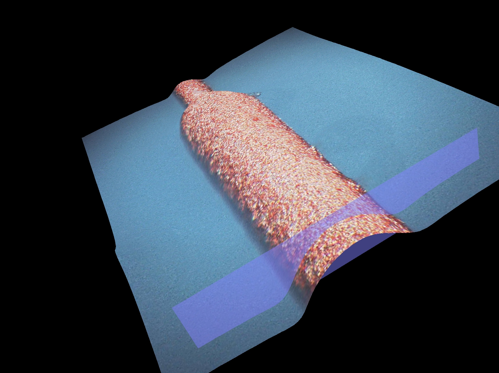
| − | - Testing wire deadening with new diameter for the last two packages: Bill recalculated the currents/timing and one sample was made. It turned out the surface looks more rough that before (see microscope picture attached). | + | - Testing wire deadening with new diameter for the last two packages: Bill recalculated the currents/timing and one sample was made. It turned out the surface looks more rough that before (see microscope picture attached). Bill will add another electro-polishing cycle to smooth the surface and will try it on another sample. |
| + | |||
| + | - All the pre-amp cards and cooling tubes were put on the first package. All HV cables were routed on the package and Chris made the connections to the HV connector (see attached pictures). All positive HV cables are bundled on the upper side of the package and all the negative HV run on the down side. To help the installation the package was installed on the supporting frame to allow its rotation. | ||
== Engineering == | == Engineering == | ||
| − | - | + | - We discussed how to run/attached the ground cable (0.5" thick!). There will be a copper plate on each package connecting together the ground cable with the detector ground and HV return cables. Bill needed the cable specs from Chris to do the design. |
| − | - | + | - Bill is designing the tool for plugging the LV connectors and working also on the cooling system. |
== Electronics == | == Electronics == | ||
| − | - Chris: | + | - Chris: seven pre-amp sets (each 22 cards) are ready and installed on the chambers. Out of them maybe 4-5 cards were out of specs, but Cody would know this better. Chris just finished testing (during the meeting) 32 flat cables to be used between the translator boards and the TDCs for the package testing in 126. 4 more are needed. Will do also 17 LV cables for the tests. 14 of them will have 8 connectors for the cathodes and 3 with 4 connectors for the wires. Lubomir will specify the distance between the connectors. |
| − | - | + | - Final LV scheme per package will have 6 cables with 2 connectors 3 inch apart for the wires, and two cable types for the cathodes with 4 connectors: type-1 6 inches apart and type-2 5-8.5-4 inches distance between |
| + | connectors. Had to increase the distances by 1/2" from the nominal values due to the 1/2" precision that the company can do. | ||
| + | |||
| + | <!-- | ||
- Lubomir tested in place the new LV scheme using three types of cathode cables with the four connectors at distances of 4-4-4" (8pc per package), 7-4-4" (14pc),and 4-9.5-4" (5pc). These lengths take into account that cables may run outside of the cooling tubes. The cables will have different colors and the connectors have to be painted somehow as well. Bill suggested how to put additional labels on the LV connectors if needed. Connecting these at some places is tricky and Bill will design a tool for that. | - Lubomir tested in place the new LV scheme using three types of cathode cables with the four connectors at distances of 4-4-4" (8pc per package), 7-4-4" (14pc),and 4-9.5-4" (5pc). These lengths take into account that cables may run outside of the cooling tubes. The cables will have different colors and the connectors have to be painted somehow as well. Bill suggested how to put additional labels on the LV connectors if needed. Connecting these at some places is tricky and Bill will design a tool for that. | ||
Revision as of 17:31, 19 January 2012
January 19, 2012 FDC meeting
Agenda
- Production Construction Tracking (Dave)
- Production update
- First package cabling
- Engineering update new diameter wire deadening,[1] (Bill)
- Electronics update (Chris)
- Pre-amp cards
- LV cabling
- Testing in 126 (Beni)
- Other
![[1]](http://www.jlab.org/Hall-D/detector/fdc/wire_deadening/Lrg-dia_w1_x1000_center1-3d.jpg)
Minutes
Participants: Bill, Dave, Chris, Simon, Beni, Eugene, and Lubomir.
Production
- Dave: working on the first cell of the third package. Wire frame was strung, but two field wires (next to each other) showed lower tension (106g instead of 130g nominal, but actually mean measured value is around 120g). Could be because of local frame deformation so that wires are touching the board with some friction, so when raising the wire frame try not to touch the wires. Could be also some garbage on the pulley or on the rod. One type-1 cathode is ready, two type-3 waiting for the daughter cards to be glued. Wire frame for the second cell is ready for stringing.
- Testing wire deadening with new diameter for the last two packages: Bill recalculated the currents/timing and one sample was made. It turned out the surface looks more rough that before (see microscope picture attached). Bill will add another electro-polishing cycle to smooth the surface and will try it on another sample.
- All the pre-amp cards and cooling tubes were put on the first package. All HV cables were routed on the package and Chris made the connections to the HV connector (see attached pictures). All positive HV cables are bundled on the upper side of the package and all the negative HV run on the down side. To help the installation the package was installed on the supporting frame to allow its rotation.
Engineering
- We discussed how to run/attached the ground cable (0.5" thick!). There will be a copper plate on each package connecting together the ground cable with the detector ground and HV return cables. Bill needed the cable specs from Chris to do the design.
- Bill is designing the tool for plugging the LV connectors and working also on the cooling system.
Electronics
- Chris: seven pre-amp sets (each 22 cards) are ready and installed on the chambers. Out of them maybe 4-5 cards were out of specs, but Cody would know this better. Chris just finished testing (during the meeting) 32 flat cables to be used between the translator boards and the TDCs for the package testing in 126. 4 more are needed. Will do also 17 LV cables for the tests. 14 of them will have 8 connectors for the cathodes and 3 with 4 connectors for the wires. Lubomir will specify the distance between the connectors.
- Final LV scheme per package will have 6 cables with 2 connectors 3 inch apart for the wires, and two cable types for the cathodes with 4 connectors: type-1 6 inches apart and type-2 5-8.5-4 inches distance between connectors. Had to increase the distances by 1/2" from the nominal values due to the 1/2" precision that the company can do.