Difference between revisions of "Fiber Tests at Regina"
| Line 13: | Line 13: | ||
== Data and Analysis == | == Data and Analysis == | ||
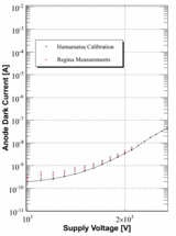
| − | The PMTs used in this setup were calibrated by Hamamatsu. To check the validity of the calibration information provided with the PMTs, the dark current was measured and compared with reference values from Hamamatsu. The graph below shows the measured dark current compared to the reference dark current for Hamamatsu PMT R329-02 0000. This PMT was operated at a bias of 1750V, so based on the calibration information from Hamamatsu, the corresponding gain at 1750V is 1.7 ± 0.1 where the uncertainty is assigned to reflect the uncertainty in the dark current measurements. | + | The PMTs used in this setup were calibrated by Hamamatsu. To check the validity of the calibration information provided with the PMTs, the dark current was measured and compared with reference values from Hamamatsu. The graph below shows the measured dark current compared to the reference dark current for Hamamatsu PMT R329-02 0000. This PMT was operated at a bias of 1750V, so based on the calibration information from Hamamatsu, the corresponding gain at 1750V is (1.7 ± 0.1) × 10<sup>7</sup> where the uncertainty is assigned to reflect the uncertainty in the dark current measurements. |
[[Image:PMTCalib.gif|160px]] | [[Image:PMTCalib.gif|160px]] | ||
| − | The actual number of photoelectrons | + | The actual number of photoelectrons detected by the PMT can be determined by a simple calculation: |
| + | : <math>\oint_{C} x^3\, dx + 4y^2\, dy</math> | ||
| + | : <math>\sum_{n=0}^\infty \frac{x^n}{n!}</math> | ||
| + | |||
The ADC spectra of the PMT 1.88 m away from a Sr-90 source are shown here for each fiber that was tested: | The ADC spectra of the PMT 1.88 m away from a Sr-90 source are shown here for each fiber that was tested: | ||
Revision as of 15:58, 28 August 2008
Experimental Setup
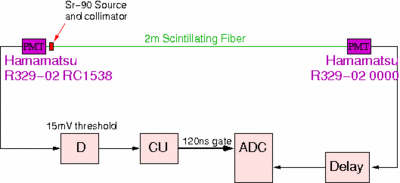
Tests were completed in Regina to measure the number of photoelectrons detected by an XP2020 PMT coupled to a 2m-long scintillating fiber excited by a Strontium-90 source located approximately 2m away from the photo cathode. The experimental setup is relatively simple and can be seen in the figure below.
The scintillating fiber was coupled at each end to a calibrated Hamamatsu XP2020 PMT using a small amount of optical grease. The signal from the PMT nearest to the Sr-90 source is used to start the ADC gate after being sent to a discriminator (D) where the threshold is set at 15 mV and a coincidence unit (CU) where the gate width is set at 120 ns. The other PMT which is located approximately 2m away from the Sr-90 source is delayed by about 40 ns before being sent to the ADC unit.
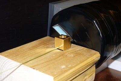
Several different fibers were measured using this setup. Each fiber was polished at both ends using a FiberFin 4 fiber polisher before being coupled to the PMTs. The fiber fits into a 1mm-diameter hole drilled through a piece of brass (see the above picture) and the Sr-90 source sits snugly in an opening directly above the fiber in that same piece of brass. A 5mm-long hole of 0.5mm-diameter is drilled through the brass perpendicular to the fiber and is used to collimate the source. The entire setup was located inside a light-sealed black box, and for added light protection the room lights remained off while measurementes were taken.
Data and Analysis
The PMTs used in this setup were calibrated by Hamamatsu. To check the validity of the calibration information provided with the PMTs, the dark current was measured and compared with reference values from Hamamatsu. The graph below shows the measured dark current compared to the reference dark current for Hamamatsu PMT R329-02 0000. This PMT was operated at a bias of 1750V, so based on the calibration information from Hamamatsu, the corresponding gain at 1750V is (1.7 ± 0.1) × 107 where the uncertainty is assigned to reflect the uncertainty in the dark current measurements.
The actual number of photoelectrons detected by the PMT can be determined by a simple calculation:
The ADC spectra of the PMT 1.88 m away from a Sr-90 source are shown here for each fiber that was tested:


