Difference between revisions of "Alarms for voltages (Nerses)"
From GlueXWiki
| Line 11: | Line 11: | ||
|- | |- | ||
| δ | | δ | ||
| − | | | + | | 0.5V |
| 0.1V | | 0.1V | ||
| 0.5V | | 0.5V | ||
Revision as of 22:13, 16 April 2014
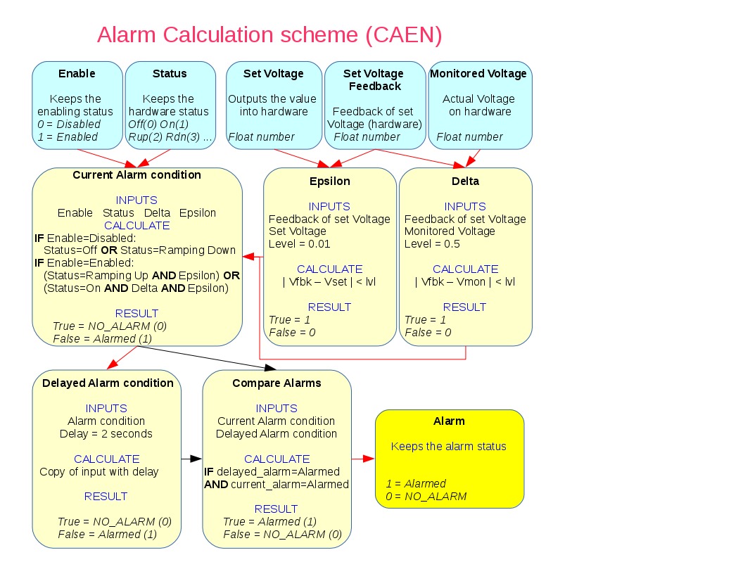
 Blocks with cyan background are inputs for alarm calculation, pale yellow blocks are intermediate calculations and yellow one is final storage of alarm state. Red arrow indicate transfer of information with Passive Processing, black arrows with No Passive Processing.
The δ and ε are different parameters for CAEN HV, WIENER LV abd BIAS modules.
| CAEN HV | WIENER LV | WIENER BIAS | |
| δ | 0.5V | 0.1V | 0.5V |
| ε | 0.01V | 0.01V | 0.01V |
Calcout record is recalculated and alarm state changed subsequently if one of inputs are changed achieved using posted monitors on input channels.