Mini BCAL for EIC
From GlueXWiki
Contents
References
- Beam Test slides for PS Setup
- mini-BCAL-study in EEL118.
- mini BCAL in Hall-D for updates on the setup at the Hall.
- Run Log COMING SOON (runs 121049 onward)
Beam Test Checklist
Checklist 1 (in EEL 118)
Go over Jon’s PS setup plugin and ensure it works. Familiarize yourselves with the quantities in the ROOT tree.-
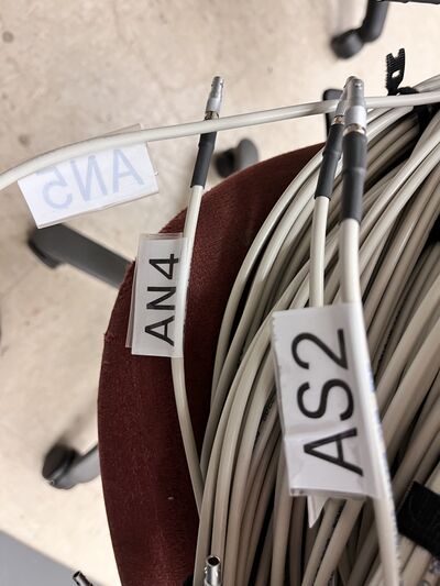
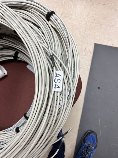
Get a label maker and make cables to match Jon’s N/S 0-15 labels.- The labelling has been done.
- AS[0-15] corresponds to the
- AN[0-15] corresponds to the ADC channels located not on the North side of the mini BCAL
- Currently 2 LEMO cables are being used for testing in EEL 118 which should be labelled.
- There is 1 LEMO cable (31 available instead of 32). Should ask Chris to arrange for one more.
- Label AN11, AN14, and AN15 using the 2 testing cables and ask Chris for the missing LEMO cable.
- Start planning the crate-slot-channel assignment with Sasha and match it to Jon’s plugin.
- This will be done during the installation time in the Hall
- Speak with Sasha about using the PS counters (fine-grained) in addition to the PSC ones (coarse-grained) for coincidences with the Mini BCAL (hardware and software coincs). Discuss the philosophy with him.
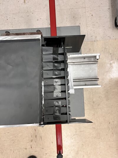
- In EEL 118 ensure the Mini BCAL is connected to its SiPM assemblies (note that North and South get mirror assemblies so that S0 is across N), etc.; Keith or Scot or Tim might help. Locate a scope and the power supplies (Chris).
- The results of the study are summarized in [mini-BCAL-study]
- Power up the SiPMs at OB=0.9V with the ISEG module and also their +/-5V amplifiers with the MPOD module. Check their signals on the scope. Measure rise time, decay time, plus height on the scope and comment on signal shape. Take photos with the scope or your phone. Do all 32 channels, using the same LEMO cable.
- The results of the study are summarized in [mini-BCAL-study]
- Check all 32 cables on a single working SiPM. (Steps 5 and 6 can be merged, to do each SiPM test with its own cable).
- This is not done. Most of the cables are labelled but are not checked yet
- If time permits, repeat step 5 with 1.4 V (and 1.2 V).
- Sasha mentioned we could do this probably while the setup is moved into the Hall. The ISEG controller in EEL 118 does not currently support fine-tuning of the voltages.
- 1. Documents for refernece to the OB to modules? 2. Document reference having relation between OB and pulse amplitude
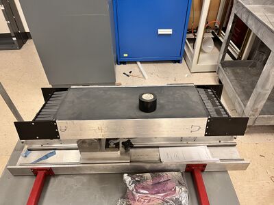
- Darkening the mini-BCAL setup
- After discussion (Keith and Zisis). it was decided to wrap the mini BCAL in black tedlar and then with a Black cloth to ensure the setup is light tight.
- mini BCAL sensitive are has been covered with black tedlar, Check
- However, still the light guides have to be wrapped in tedlar, and when the SiPM modules are mounted it has to be wrapped as well.
- Should this wrapping be done while in the Hall?, If we plan to move the setup with SiPM modules detached? Or should we attach the SiPMs, wrap and do the move?
- Document your results in the log.
- After conferring with me, if all looks good, uncable and coil all LEMO cables nicely, for a move to the Hall.
- Disconnect power.
- Disconnect SiPM assemblies and wrap them in bubble wrap for more to the hall.
- Speak with Chris & Sasha about which ISEG and MPOD will be used in the Hall.
Checklist 2 (in Hall)
-
Monday morning: We will meet at 8:45 am in the counting house for the morning meeting. During that meeting, with everyone present, decide on Hall D access. - After that we will coordinate the move with Tim and Scot.
- Move sciglass to make room for Mini BCAL. (Sasha, Tim, Scot).
- Set up a test stand behind the sciglass, as close as possible to the beam pipe. (Scot/Tim).
- Move Mini BCAL and all its parts from EEL118 to Hall D. This will go in through the ramp to the hall (too heavy to carry down the steps).
- Take a scope down to Hall D (if there is not one there already that we can use).
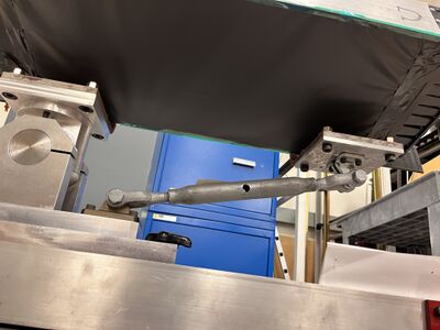
- Install Mini BCAL on the test stand and roughly align. Discuss alignment with Tim.
- Connect cables at Mini BCAL and thread through the floor to FADCs (Sasha, Scot). Record crate-slot-channel addresses.
- Connect power and preamps.
- Power the system up in the hall and look at signals on the scope in the hall (super quick).
- Check with Sasha to ensure the GlueX run config file interrogates the FADC crate.
- Check in the counting-house once the first GlueX data run is taken by running the above plugin over one of the first EVIO files. Look at ROOT tree quantities.
- If we get another Hall Access, we could tilt the BCAL or move it sideways. Let’s discuss this with Sasha and decide early next week.
Check out mini BCAL in Hall-D for updates on the setup at the Hall.
Photographs
Scripts
- For the input, Sasha made several shell scripts, to switch on, off, and set voltages to the output channels using net-SNMP protocols to the wiener MPOD controller
- The scripts can be found at
hdhops/bcal_prot -
set_lv_on,set_lv_offswitches on/off all the low voltages on.
Data Streaming
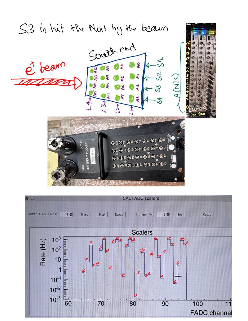
The way the mini BCAL is set up Sector 3 (index from 1) is hit the most that can be seen from the Scalars
Relevant Logbook Entries
- First look at mini BCAL data (3/7/23)
- Repositioning of SciGlass (3/18/23)
- Repositioning of mini BCAL and raw mode run log (3/19/23)
- Quick sketch of final mini BCAL position (3/28/23)
Analysis
- ROOT plugin: coming soon
