SiPM Radiation Hardness Test
From GlueXWiki
SiPM Radiation Hardness Test in Hall A
Test Plan
System Diagram
Device List
- Control Computer: transversity.jlab.org: (129.57.164.28)
- GPIB over IP: GPIB-ENET/100: agpib.jlab.org (129.57.192.73)
- Serial Port Server: ESP904: portservha50.jlab.org (129.57.192.78)
- USB over IP: AnywhereUSB/5: ausb.jlab.org (129.57.192.75)
- Oscilliscope: TDS3034: dosci.jlab.org (129.57.192.77)
- Power Outlet: APC Outlet Control: hlauser:hlauser@hareboot12.jlab.org (129.57.192.76)
- Outlet 1: Pulse Generator
- Outlet 2: Temperature Box
- Outlet 3: Oscilliscope
- Outlet 4: GPIB over IP
- Outlet 5: Power Supply for Hamamatsu Unit
- Outlet 6: Power Supply for SensL Unit
- Outlet 7: Picoamp Meter
- Outlet 8: Serial Port Server
- USB to Serial HUB: ComHUB
- Serial 1: Power Supply for Hamamatsu Unit
- Serial 2: Power Supply for SensL Unit
- Serial 3: Oscilliscope
- Serial 4: Temperature Box
- Picoamp Meter x2: Keithley-485 (GPIB)
- GPIB Address: 1 (Hamamatsu); 2 (SensL)
- Pulse Generator: HP-8116A (GPIB)
- GPIB Address: 4
- Power Supply x2: B&K-1787B (RS232)
- Temperature Meter: CN77544 (RS232)
2010 Mar 17
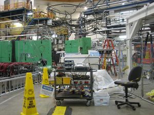
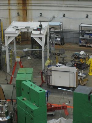
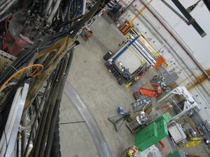
- photos of SiPM test setup
2010 Mar 18
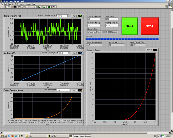
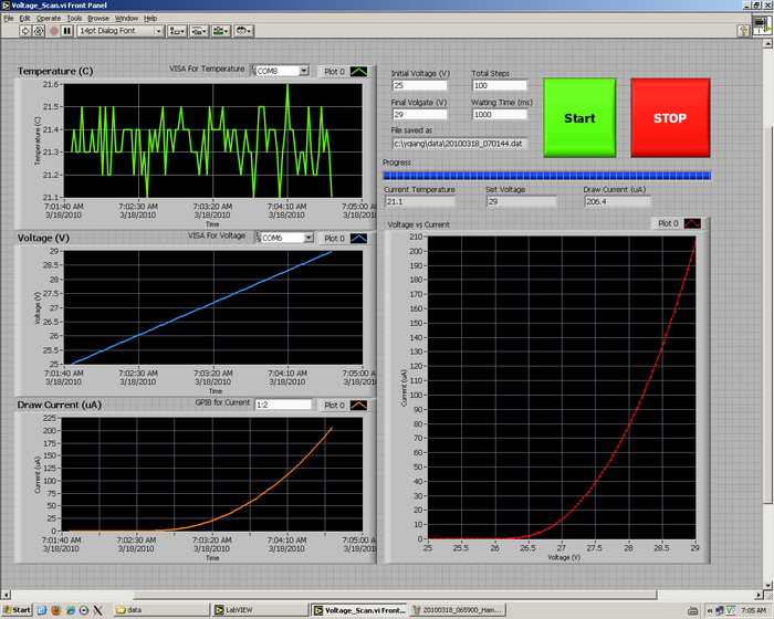
- Hamamatsu SiPM Draw Current vs Bias Voltage
- SensL SiPM Draw Current vs Bias Voltage
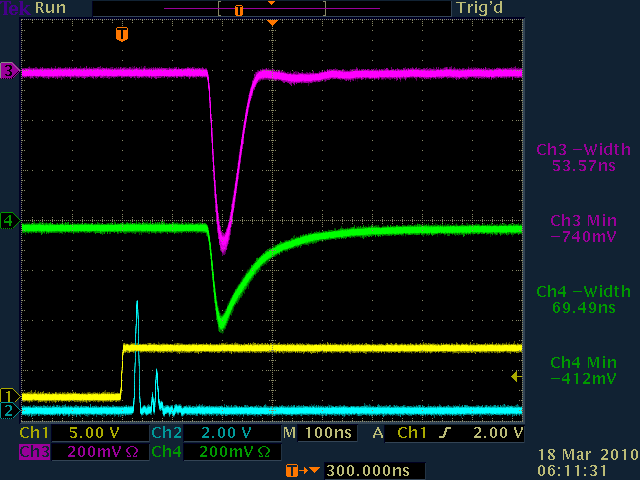
- Signals on Oscilliscope with 70.5V on Hamamatsu and 28.5V on SensL
