Baby BCAL at JLab Photos
From GlueXWiki
Contents
PS Test Stand Setup (March 2023)
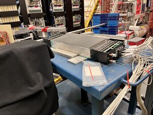
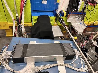
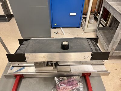
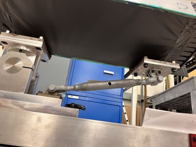
The baby BCAL was set up on the test bench. Downstream is defined as the North end and the Upstream is defined as the South End
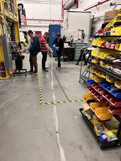
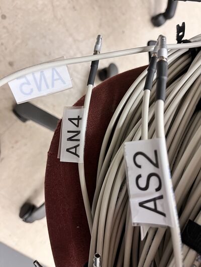
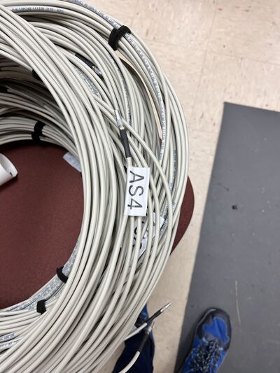
Cable stretching
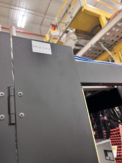
The North and south end cables were grouped together and stretched across cables crates over to the DAQ.
Module Assignment
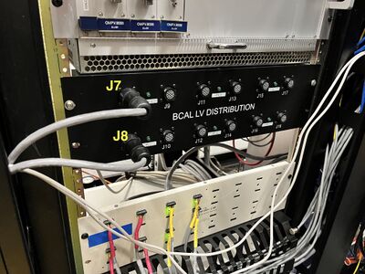
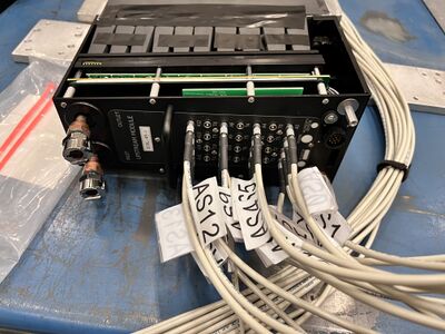
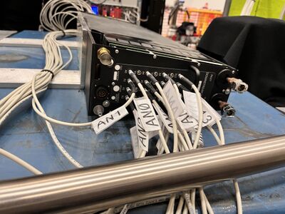
| Module Name | HV/LV BCAL Distribution Box | Direction | Module Picture | Bias Voltage (module) |
|---|---|---|---|---|
| Upstream 49 | South | 75 V | ||
| Downstream 49 | |
North | 74 V |
Wrapping the BCAL
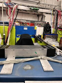
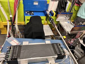
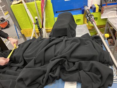
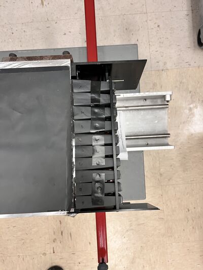
The baby BCAL was wrapped in black Tedlar after mounting the SiPM modules and connecting the LEMO output cables. After wrapping the BCAL was covered using a black cloth to make it light tight
DAQ Crate assignment
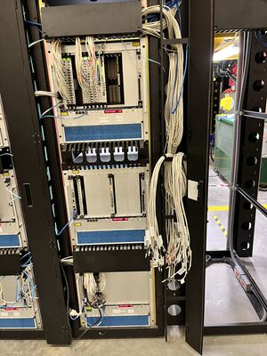
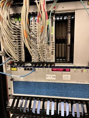
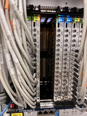
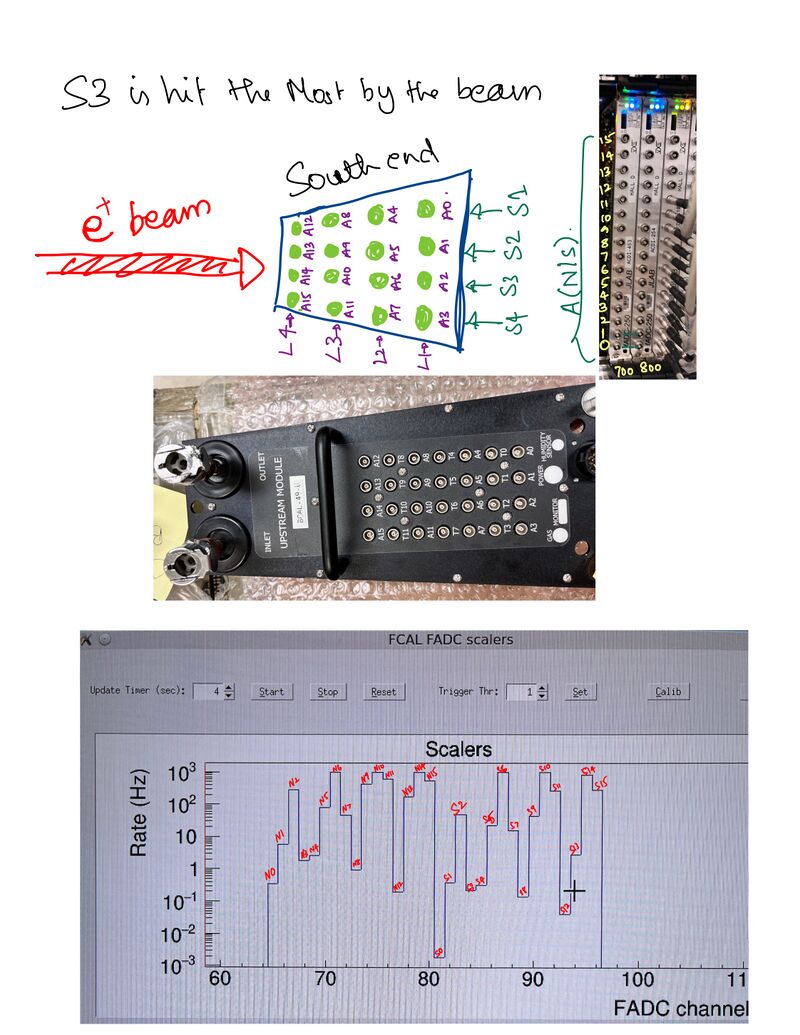
The output channels from the baby BCAL is connected to the following fADC crates.
Data Streaming
The way the mini BCAL is set up Sector 3 (index from 1) is hit the most that can be seen from the Scalars
