Cables and Crates
From GlueXWiki
Calorimeter Layout
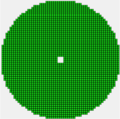
Fig. 1 FCAL layout
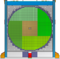
Fig. 2 FCAL 2 layout


VXS crate layout
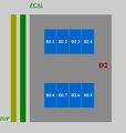
Fig. 1 Twelve FCAL VXS crates
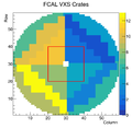
Fig. 2 Connection of FCAL signal cables to 12 VXS crates. Red box denotes the FCAL insert region.
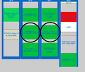
Fig. 3 Six FCAL crates on the north side. Circles denote crates connected to the FCAL2 insert region.
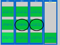
Fig. 4 Six FCAL crates on the south side. Circles denote crates connected to the FCAL2 insert region.


VXS crates connected to the FCAL2 insert region
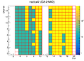
Fig. 1 Channel assignment (rocfcal2, north)
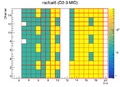
Fig. 2 Channel assignment (rocfcal5, north)
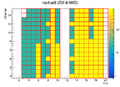
Fig. 3 Channel assignment (rocfcal8, south)
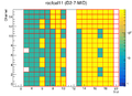
Fig. 4 Channel assignment (rocfcal11, south)


