Difference between revisions of "CDC HVB version 3"
From GlueXWiki
m |
m |
||
| Line 7: | Line 7: | ||
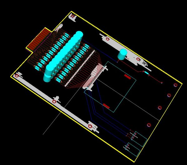
[[Image:pcbv3.jpg|thumb|none|600px|figure 2.1: A 3D representation of the HVB.]] | [[Image:pcbv3.jpg|thumb|none|600px|figure 2.1: A 3D representation of the HVB.]] | ||
| + | |||
| + | |||
| + | The HV connector will most likely be: | ||
| + | |||
| + | Tyco: 1218055-1 surface mount on the HVB side | ||
| + | Tyco: 448660-1 on the cable side | ||
| + | |||
| + | |||
| + | The LV/test-signal/T-readout cable will most like be: | ||
| + | |||
| + | Erni: 214014 surface moutn on the HVB side | ||
| + | Erni: SFX with 8 conductors on the cable side | ||
Revision as of 14:20, 13 May 2008
Can be downloaded here:
A representation can be seen in figure 2.1. Note: this is a 3D representation: the grounding plane is not shown and the (blue) RC devices are meant to be SM (if you look close enough you can see the SM pads) but are not shown as such (there was no 3D representation available for SM devices).
The HV connector will most likely be:
Tyco: 1218055-1 surface mount on the HVB side Tyco: 448660-1 on the cable side
The LV/test-signal/T-readout cable will most like be:
Erni: 214014 surface moutn on the HVB side Erni: SFX with 8 conductors on the cable side
