Difference between revisions of "Minutes-1-3-2013"
| Line 8: | Line 8: | ||
# Tests at EEL126 [https://halldweb1.jlab.org/elog-halld/FDC FDC E-log] | # Tests at EEL126 [https://halldweb1.jlab.org/elog-halld/FDC FDC E-log] | ||
# Other | # Other | ||
| − | |||
| − | |||
= Minutes = | = Minutes = | ||
| Line 17: | Line 15: | ||
== Production == | == Production == | ||
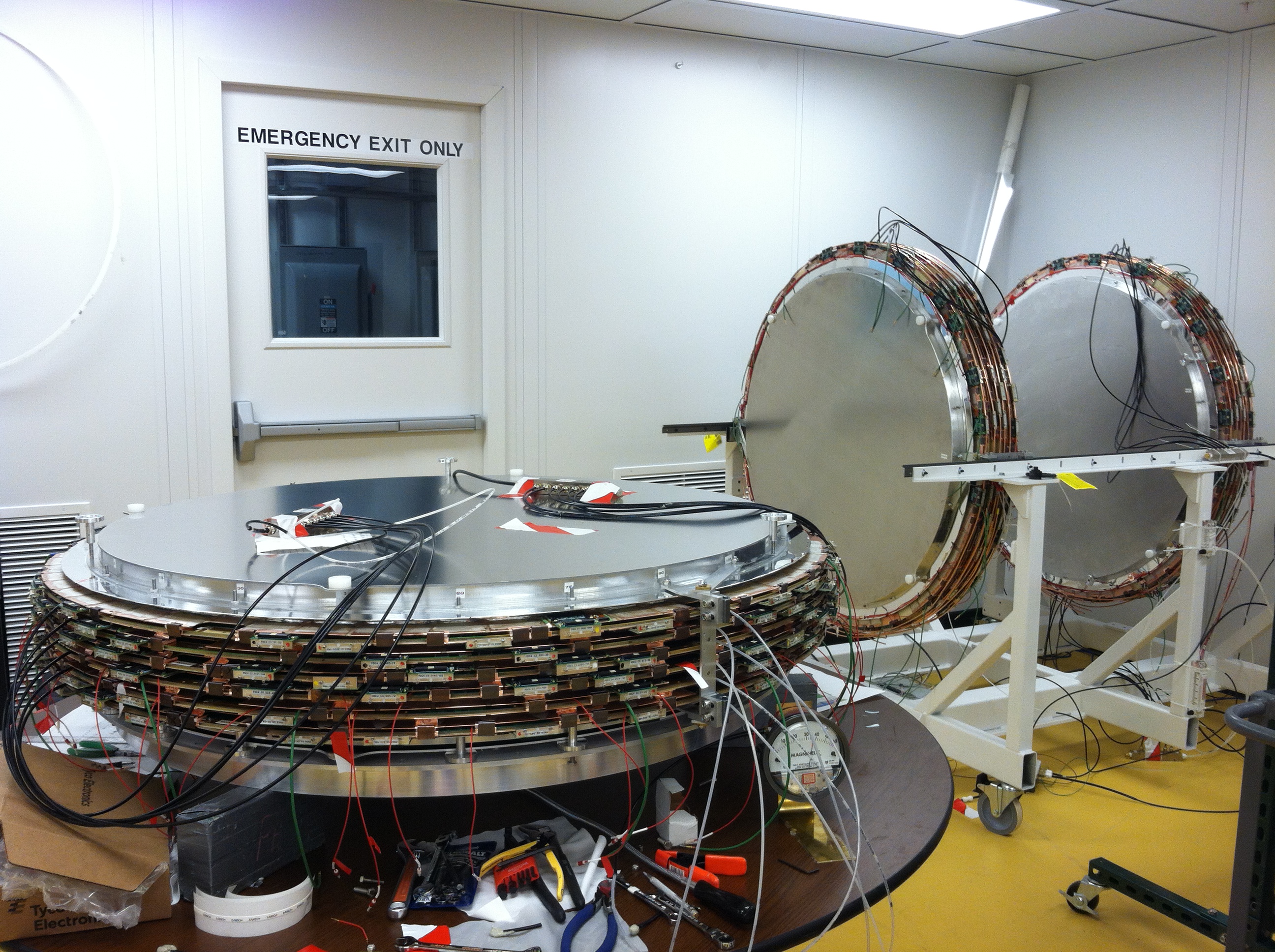
| − | - | + | - Picture done before Christmas of the the packages #4,1,3 (front to back) is linked above. Now we have also the colling loops installed on package #4, HV wiring done, tomorrow Chris and Nick will finish the HV connectors and the package will be ready for testing at EEL126. What's not in the picture: package #2 with three cells assembled. All four packages were flushed with Nitrogen over the holidays and yesterday we switched the gas to Ar/CO2 mixture for package #2, will start testing it next week. |
| − | - | + | - Dave: working on the last two cathodes (#75-76) needed for the last production package #2: installing, testing, gluing daughter cards on them. Also working on three spare cathodes. Casey started working on a new spare wire frame; glued the PCB ring, now ready for lamination. We have PCBs for one more new wire frame. |
| − | - | + | - We had issues with the HVAC for the clean room starting yesterday in the morning (most likely) and this morning a steam house in the HVAC broke that was replaced by Dave. Ron Bartec said that due to power glitch the AC stopped working. Since the humidity in the bay area was low enough we never got humidity above 43% inside the clean room. The temperature there didn't exceed 74 deg. They fixed the problem and now everything is going back to normal. |
| − | + | == Cathode corrosion test == | |
| − | + | - Lubomir: test #3 (Ar/CO2 gas, at ~70degC) is completed, see the final spreadsheet attached. before Christmas the second EPDM sample failed, we stopped the test and opened the box. It turned out all sample have low resistance at the place of the O-rings, all the samples that failed were due to higher resistance on the trace next to the soldering point. So the main conclusion from this test is that there are problems doing conventional soldering on 2 microns copper traces and that these problems appear most likely before the corrosion we want to study. Therefore we need different experimental set-up if we want to continue with these tests. | |
| − | - | + | - Measuring the resistance on the trace where the O-ring sample was placed turned out to be tricky. This is due to a non-conductive layer that has developed somehow on the top of the copper close to the O-ring, so one needs a pin that will go through that layer but will make contact to the thin copper layer. Using this measurement technique Lubomir re-checked the samples that failed before. The EPDM sample from the second test that failed after 12 days at 100 deg C and 100% humidity turned out to be really corrosion below the EPDM material. However, the two EPDM samples from the first test that failed after 8-10 days showed low resistance at the trace below the EPDM; this has to be confirmed with Vlad since there were mistakes with sample labeling. In any case using the results from the three tests and assuming the activating energy is the same for the different condition, one can put a lower limit for the corrosion problem to appear when using EPDM+Viton: between 1 and 3.5 years. |
| − | + | == Engineering == | |
| − | + | <!-- | |
| − | + | ||
| − | - | + | |
| − | + | ||
| − | + | ||
- Bill ordered fiducial stuff the parts for the package spacers. All the parts for the cooling, except the chiller, are here. Will talk to the survey people about the details. | - Bill ordered fiducial stuff the parts for the package spacers. All the parts for the cooling, except the chiller, are here. Will talk to the survey people about the details. | ||
Revision as of 16:26, 3 January 2013
January 3, 2013 FDC meeting
Agenda
- Production Construction Tracking (Dave),picture of the three packages
- Corrosion tests (Lubomir)
- Engineering (Bill)
- Electronics (Chris, Nick)
- Tests at EEL126 FDC E-log
- Other
Minutes
Participants: Eugene, Bill, Dave, Chris, Nick, and Lubomir.
Production
- Picture done before Christmas of the the packages #4,1,3 (front to back) is linked above. Now we have also the colling loops installed on package #4, HV wiring done, tomorrow Chris and Nick will finish the HV connectors and the package will be ready for testing at EEL126. What's not in the picture: package #2 with three cells assembled. All four packages were flushed with Nitrogen over the holidays and yesterday we switched the gas to Ar/CO2 mixture for package #2, will start testing it next week.
- Dave: working on the last two cathodes (#75-76) needed for the last production package #2: installing, testing, gluing daughter cards on them. Also working on three spare cathodes. Casey started working on a new spare wire frame; glued the PCB ring, now ready for lamination. We have PCBs for one more new wire frame.
- We had issues with the HVAC for the clean room starting yesterday in the morning (most likely) and this morning a steam house in the HVAC broke that was replaced by Dave. Ron Bartec said that due to power glitch the AC stopped working. Since the humidity in the bay area was low enough we never got humidity above 43% inside the clean room. The temperature there didn't exceed 74 deg. They fixed the problem and now everything is going back to normal.
Cathode corrosion test
- Lubomir: test #3 (Ar/CO2 gas, at ~70degC) is completed, see the final spreadsheet attached. before Christmas the second EPDM sample failed, we stopped the test and opened the box. It turned out all sample have low resistance at the place of the O-rings, all the samples that failed were due to higher resistance on the trace next to the soldering point. So the main conclusion from this test is that there are problems doing conventional soldering on 2 microns copper traces and that these problems appear most likely before the corrosion we want to study. Therefore we need different experimental set-up if we want to continue with these tests.
- Measuring the resistance on the trace where the O-ring sample was placed turned out to be tricky. This is due to a non-conductive layer that has developed somehow on the top of the copper close to the O-ring, so one needs a pin that will go through that layer but will make contact to the thin copper layer. Using this measurement technique Lubomir re-checked the samples that failed before. The EPDM sample from the second test that failed after 12 days at 100 deg C and 100% humidity turned out to be really corrosion below the EPDM material. However, the two EPDM samples from the first test that failed after 8-10 days showed low resistance at the trace below the EPDM; this has to be confirmed with Vlad since there were mistakes with sample labeling. In any case using the results from the three tests and assuming the activating energy is the same for the different condition, one can put a lower limit for the corrosion problem to appear when using EPDM+Viton: between 1 and 3.5 years.