Difference between revisions of "Distribution of signals and voltages"
From GlueXWiki
| Line 5: | Line 5: | ||
<gallery> | <gallery> | ||
| − | Image:fcal_dr1. | + | Image:fcal_dr1.jpg | Fig. 1 Twelve FCAL VXS crates |
| − | Image:fcal_dr2. | + | Image:fcal_dr2.jpg | Fig. 2 Connection of FCAL signal cables to 12 VXS crates. Red box denotes the FCAL insert region. |
| − | Image:fcal_dr3. | + | Image:fcal_dr3.jpg | Fig. 3 Six FCAL crates on the north side. Circles denote crates connected to the FCAL2 insert region. |
| − | Image:fcal_dr4. | + | Image:fcal_dr4.jpg | Fig. 4 Six FCAL crates on the south side. Circles denote crates connected to the FCAL2 insert region. |
</gallery> | </gallery> | ||
Revision as of 14:55, 30 March 2023
Original layout the distribution boards and cables
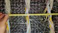
Fig. 1 Twelve FCAL VXS crates
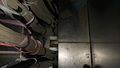
Fig. 2 Connection of FCAL signal cables to 12 VXS crates. Red box denotes the FCAL insert region.
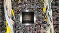
Fig. 3 Six FCAL crates on the north side. Circles denote crates connected to the FCAL2 insert region.
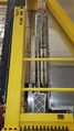
Fig. 4 Six FCAL crates on the south side. Circles denote crates connected to the FCAL2 insert region.


