Difference between revisions of "Construction of Low-Granularity counters"
(→Light Leakage Test) |
(→PSC Insulation Assembly) |
||
| (67 intermediate revisions by 2 users not shown) | |||
| Line 654: | Line 654: | ||
==Installation== | ==Installation== | ||
<b>EXPECTED JUNE-JULY 2014</b> | <b>EXPECTED JUNE-JULY 2014</b> | ||
| + | |||
| + | ===Materials=== | ||
| + | |||
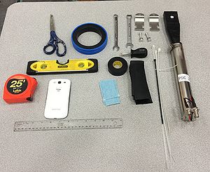
| + | The materials used throughout the PSC installation process. | ||
| + | |||
| + | • Electrical tape | ||
| + | |||
| + | • ~10 Zip Ties | ||
| + | |||
| + | • 32 Uni-strut clamps | ||
| + | |||
| + | • 1 Bubble Level -1m | ||
| + | |||
| + | • 1 Bubble Level -1ft | ||
| + | |||
| + | • 1 Pair of scissors | ||
| + | |||
| + | • 1 Box cutter | ||
| + | |||
| + | • Ruler | ||
| + | |||
| + | • Measuring tape | ||
| + | |||
| + | • Camera | ||
| + | |||
| + | • Insulation (Neoprene Rubber ~1.5mm thick) | ||
| + | |||
| + | • Nylon String | ||
| + | |||
| + | • 1 7/16" Wrench | ||
| + | |||
| + | • 1 1/2" Wrench | ||
| + | |||
| + | <table border=0> | ||
| + | <tr><td> | ||
| + | [[File:Materials cropped.jpg|thumb|300px|'''Figure 33.''' Materials]]</td><td> | ||
| + | </table> | ||
| + | |||
| + | ===PSC Insulation Assembly=== | ||
| + | |||
| + | The machining of the four sets of transverse uni-strut bars was not as precise to one another as would be prefered. There were minor errors in the distance of each set perpendicularly from the center-line position. This caused problems in the depth between the scintillator locations, namely, the north side rack and south side rack had different z-axis positions for the scintillators. To adjust for this the insulation was not applied uniformly to every PSC, but differed based on the rack it was clamped to. | ||
| + | |||
| + | The north rack had a significantly larger gap between the scintillators, creating a problem. To remedy this problem, as best we could, the insulation between the PSC mu-metal casing and the sets of uni-strut bars was kept to a minimum. Only a single thick layer of vinyl electrical tape was wrapped completely around the tube to prevent any scratching or grounding of the PSCs. This made it so we were able to keep the gap to a maximum of 2-4 mm. The southern rack had considerable less space between the scintillator heads compared to the northern rack. This meant that the minimal insulation of the other PSCs would not work in this case. To compensate for the distance we added two thin strips of neoprene rubber (~1.5mm in thickness, and 5cm long) where the uni-strut bars met the PSC metal casing. These neoprene rubber strips were held in place with two lengthwise strips of electrical tape and then vinyl electrical tape was wrapped around the circumference of the entire PSC, similar to the north rack design.Using this method we were able to both insulate the detectors and provide enough space to ensure the scintillator heads were not applying stress to one another. | ||
| + | |||
| + | <table border=0> | ||
| + | <tr><td> | ||
| + | [[File:IMAG1038.jpg|thumb|300px|'''Figure 35.''' Cutting insulation]]</td><td> | ||
| + | [[File:IMAG1048 (2).jpg|thumb|300px|'''Figure 36.''' Uniform Neoprene Strips]]</td><td> | ||
| + | [[File:IMAG1049 (2).jpg|thumb|300px|'''Figure 37.''' Neoprene with Tape]]</td></tr> | ||
| + | <tr><td> | ||
| + | [[File:IMAG1052.jpg|thumb|300px|'''Figure 38.''' Chris Wrapping a PSC]]</td><td> | ||
| + | [[File:IMAG1055.jpg|thumb|300px|'''Figure 39.''' Wrapped PSC]]</td><td> | ||
| + | </table> | ||
| + | |||
| + | ===Installation=== | ||
| + | ====Procedure==== | ||
| + | |||
| + | 1. Gather all materials listed. | ||
| + | |||
| + | 2. Make proper measurements. | ||
| + | |||
| + | • Distance between each uni-strut on top set and bottom set. | ||
| + | |||
| + | • Distance between top set of uni-struts and bottom set of unistruts. | ||
| + | |||
| + | • Distance of height on the frame which intersects the beam line. | ||
| + | |||
| + | • Distance from beam line to first PSC. | ||
| + | |||
| + | • Width of uni-strut clamp. | ||
| + | |||
| + | 3. Cut thirty-two strips of insulating material equal to circumference of each PSC and ~1 cm greater width than that of the clamp. | ||
| + | |||
| + | 4. Apply a strip of electrical tape lengthwise on top and bottom of insulating material, leaving an excess of one cm on the left of the material for fastening. | ||
| + | |||
| + | 5. Wrap insulating material on PSC at proper clamp position, determined through measurements. | ||
| + | |||
| + | 6. Place a PSC at the correct distance from the beam line (provided by Sasha, approximately 22cm) making sure to line up the center mark on the scintillator parallel to the beam | ||
| + | line. | ||
| + | |||
| + | 7. Tighten clamps by hand. | ||
| + | |||
| + | 8. Measure and adjust center position if needed. | ||
| + | |||
| + | 9. Tighten clamps firmly with wrench, being careful not to stress the mu-metal. | ||
| + | |||
| + | 10. Repeat from step “5.” with the next seven PSCs, making sure to overlap each successive PSC scintillator 2mm with the previous PSC scintillator. | ||
| + | |||
| + | 11. Successive scintillators should alternate between top and bottom rack positions. | ||
| + | |||
| + | 12. Use bubble level to maintain center line position. | ||
| + | |||
| + | 13. Run cabling to each respective PSC making sure to not leave excess wire by tying off with zip ties. | ||
| + | |||
| + | 14. Ensure the power supply is not delivering high voltage while fastening and connecting. | ||
| + | |||
| + | 15. Make adjustments as needed. | ||
| + | |||
| + | |||
| + | The insulated PSCs were organized according to the following translation diagram ('''Figure 40.''' Below). We tied a nylon string at the center beamline position and used a one-meter bubble level to make sure the string was at the necessary position. This string provided a mark for the center position stickers placed on each scintillator head to ensure a more accurate installation. | ||
| + | |||
| + | One person held the PSC in position, making sure that the faces were level and its height was aligned with the nylon string while the second person then proceeded to fasten and tighten each uni-strut clamp. Using this method we could ensure than future adjustments would be minor. Once the PSCs were attached, we threaded cable via the cable racks below the floor from the splitter to a narrow hole near the bottom of the pair-spectrometer frame. The low-granularity then had both its power and signal cables divided into two groups of eight and fasted along the legs of the frame while special care taken to leave excess cable should it be needed, but not enough to become intrusive. We then connected the cables to the necessary ports on each PSC and proceeded to testing. | ||
| + | |||
| + | <table border=0> | ||
| + | <tr><td> | ||
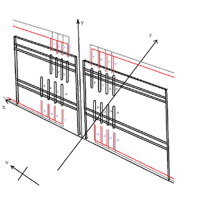
| + | [[File:Low Granularity Layout.png|thumb|300px|'''Figure 40.''' Translation of installed PSC with cabling]]</td><td> | ||
| + | [[File:IMAG1067.jpg|thumb|300px|'''Figure 41.''' Fully installed]]</td><td> | ||
| + | [[File:IMAG1068.jpg|thumb|300px|'''Figure 42.''' Corresponding photo to PSC translation]]</td></tr> | ||
| + | <tr><td> | ||
| + | [[File:JacobinInstall.png|thumb|300px|'''Figure 43.''' Jacob Installing Last PSC]]</td><td> | ||
| + | [[File:String.JPG|thumb|300px|'''Figure 34.''' Height of Beamline]]</td><td> | ||
| + | </table> | ||
| + | |||
| + | ===Post Installation Testing=== | ||
| + | |||
| + | After each PSC was mounted to the racks, we proceeded to test them using cosmic radiation. This test was designed much the same way as the pre-installation testing. To turn on the input voltage in post-installation testing we had to access the control system for Hall D's voltage system. Once the terminal was open we had to type one line: '''telnet u1-9-top 1527'''. This put us in the Hall D log-in page which we proceeded to log-in to. From this point we went to the '''Main''' heading and clicked on '''Channels''' ('''Figure 44''' Below). Here is where we could turn voltage to the channel either on or off and monitor both current(IMon) and voltage (VMon) being applied to the channel. | ||
| + | |||
| + | We used the same materials, and same general settings for the oscilloscope ('''Figure 45''' Below). Since both of the background testing practices were similar we were able to take the previously collected data taken at 1.25 kV for the pre-installation background testing and compare it to the newly collected post-installation data. | ||
| + | |||
| + | <table border=0> | ||
| + | <tr><td> | ||
| + | [[File:IMAG1083.jpg|thumb|300px|'''Figure 44.''' Control System]]</td><td> | ||
| + | [[File:IMAG1086.jpg|thumb|300px|'''Figure 45.''' Oscilloscope in Hall D]]</td><td> | ||
| + | </table> | ||
| + | |||
| + | [[Post Installation Background Testing]] | ||
| + | |||
| + | [[1250V Background Comparison]] | ||
| + | |||
| + | <table width=200 align=center border=1 rules=rows frame=void> | ||
| + | <tr><th></th><th align=center colspan=6>Monitored Voltage and Current</th></tr> | ||
| + | <tr><td>Ch. # (PSC #)</td><td>VMon (V)</td><td>IMon ( μA)</td><tr> | ||
| + | <tr bgcolor=gray><td width=50>Ch. 00 (PSC 1)</td><td>1251.0</td><td>187.0</td><tr> | ||
| + | <tr><td>Ch. 01 (PSC 18)</td><td>1251.0</td><td>185.0</td><tr> | ||
| + | <tr bgcolor=gray><td>Ch. 02 (PSC 3)</td><td>1250.5</td><td>187.5</td><tr> | ||
| + | <tr><td>Ch. 03 (PSC 4)</td><td>1250.5</td><td>186.5</td><tr> | ||
| + | <tr bgcolor=gray><td>Ch. 04 (PSC 17)</td><td>1250.5</td><td>186.5</td><tr> | ||
| + | <tr><td>Ch. 05 (PSC 6)</td><td>1250.5</td><td>187.5</td><tr> | ||
| + | <tr bgcolor=gray><td>Ch. 06 (PSC 7)</td><td>1250.5</td><td>186.0</td><tr> | ||
| + | <tr><td>Ch. 07 (PSC 8)</td><td>1250.5</td><td>186.5</td><tr> | ||
| + | <tr bgcolor=gray><td>Ch. 08 (PSC 9)</td><td>1251.0</td><td>185.5</td><tr> | ||
| + | <tr><td>Ch. 09 (PSC 10)</td><td>1251.0</td><td>185.5</td><tr> | ||
| + | <tr bgcolor=gray><td>Ch. 10 (PSC 11)</td><td>1250.5</td><td>186.5</td><tr> | ||
| + | <tr><td>Ch. 11 (PSC 12)</td><td>1251.0</td><td>186.5</td><tr> | ||
| + | <tr bgcolor=gray><td>Ch. 12 (PSC 13)</td><td>1250.5</td><td>188.0</td><tr> | ||
| + | <tr><td>Ch. 13 (PSC 14)</td><td>1251.0</td><td>186.5</td><tr> | ||
| + | <tr bgcolor=gray><td>Ch. 14 (PSC 15)</td><td>1250.0</td><td>187.0</td><tr> | ||
| + | <tr><td>Ch. 15 (PSC 16)</td><td>1250.5</td><td>185.5</td><tr> | ||
| + | <tr bgcolor=gray><td>Average</td><td>1250.7</td><td>186.47</td><tr> | ||
| + | </table> | ||
Latest revision as of 09:15, 21 July 2014
Contents
PMT Testing
Expectations
The photomultiplier tubes (i.e. 18 in all) should, in principle, all exhibit the same characteristics. All 18 should have the same change in output amplitude with a change in input potential, as well as identical time responses regardless of the input potential. Therefore, one would expect a histogram of these characteristics to show a count of 18 at a single value on the x-axis. Consequently, a logarithmic plot of the overall gains of each PMT should be 18 identical lines of positive slope.
The Hamamatsu Photomultiplier Tube (H7415) was chosen because it has the characteristics required for this pair spectrometer. This PMT will be attached to the EJ-200 organic plastic scintillator and light guide fabricated by Eljen Technology. The properties of the tube are in the table below:
| Photomultiplier Tube Assembly (H7415) | |
| Dynode Structure | Linear-focused |
| Dynode Stages | 10 |
| Max. Rating) Anode to Cathode Voltage | -2000 V |
| Anode to Cathode Supply Voltage | -1500 V |
| Anode) Gain Typ. | 5E+06 |
| (Time Response) Rise Time Typ. | 1.7 ns |
| (Time Response) Transit Time Typ. | 16 ns |
Rise time listed here was arrived at using a laser. In the testing of the PMT's at Jefferson Lab, an LED will be used, which will not produce a clean signal elimination like the laser.
Testing
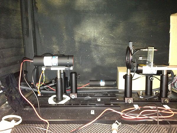
To test the PMT's, connections had to be soldered on to the wires in order to have quick connection ability to both the oscilloscope and high-voltage power source. Once this was done, the PMT was placed in a previously fabricated dark box with mounts for the tube and LED. The LED was powered by a wave generator which was set to run 8V square waves at 10 kHz with a 8 ns pulse width. Figure 1 shows the set up used for each PMT.
The LED was positioned behind a diffracted lens to spread the light out. Careful attention had to be made that each PMT was positioned at the same place on the mount in order to eliminate fluctuations in beam intensity. The anode-to-cathode potential would range from -1.1 kV to -1.5 kV.
Data
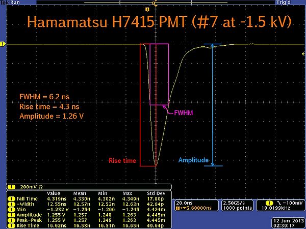
The data gathered from the oscilloscope were the amplitude and rise time. Figure 2 shows what those values represent on the oscilloscope screen. Amplitudes were measured in millivolts and the rise time was in nanoseconds.
The data for the PMT amplitudes is in the table below. At -1.1 kV, the minimum amplitude was 124 mV. At -1.5 kV, the maximum amplitude was 1660 mV.
| PMT Amplitudes (mV) | ||||||
|---|---|---|---|---|---|---|
| PMT # | -1.1 kV | -1.2 kV | -1.3 kV | -1.4 kV | -1.5 kV | |
| 1 | 171 | 303 | 513 | 833 | 1320 | |
| 2 | 124 | 219 | 365 | 583 | 906 | |
| 3 | 187 | 330 | 553 | 892 | 1400 | |
| 4 | 213 | 376 | 627 | 1010 | 1575 | |
| 5 | 216 | 387 | 657 | 1060 | 1670 | |
| 6 | 178 | 313 | 522 | 839 | 1310 | |
| 7 | 171 | 302 | 507 | 812 | 1256 | |
| 8 | 181 | 322 | 542 | 877 | 1380 | |
| 9 | 159 | 284 | 473 | 755 | 1160 | |
| 10 | 168 | 299 | 504 | 811 | 1260 | |
| 11 | 160 | 289 | 489 | 785 | 1236 | |
| 12 | 210 | 370 | 624 | 1000 | 1556 | |
| 13 | 214 | 385 | 650 | 1050 | 1660 | |
| 14 | 203 | 359 | 600 | 968 | 1500 | |
| 15 | 159 | 287 | 483 | 780 | 1215 | |
| 16 | 170 | 299 | 504 | 810 | 1300 | |
| 17 | 195 | 348 | 607 | 970 | 1500 | |
| 18 | 216 | 376 | 627 | 997 | 1550 | |
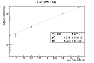
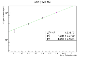
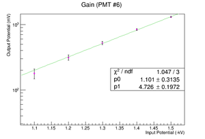
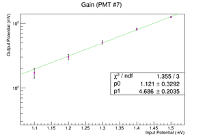
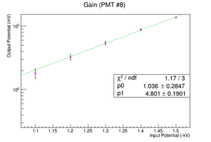
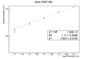
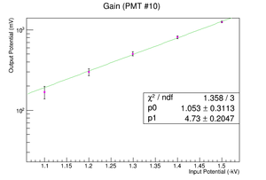
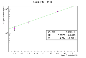
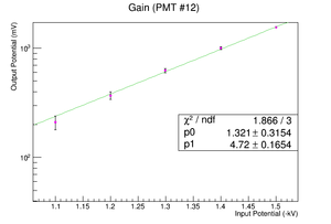
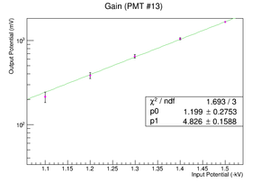
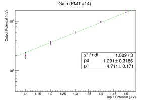
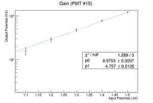
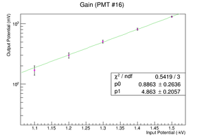
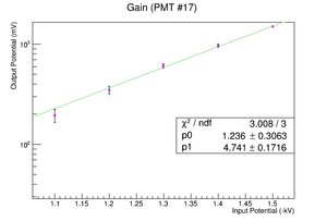
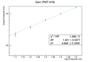
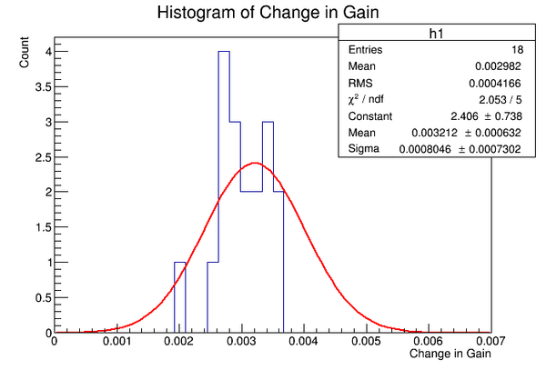
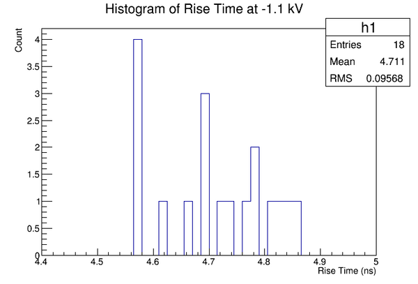
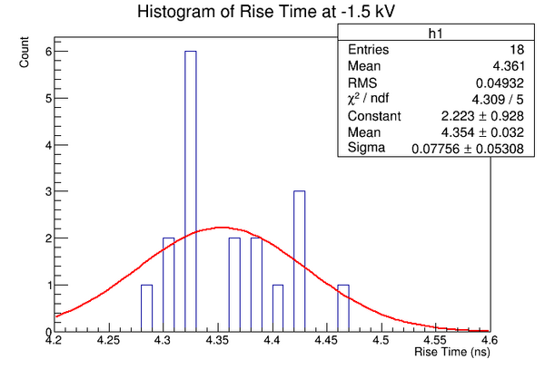
The data in the table above produced the plots located at the right side of the page.
|
| ||||||||||||||||||||||||||||||||||||||||||||||||||||||||||||||
Conclusions
From the data gathered here, one can see that the original hope that all PMT's would behave identically must be abandoned. The histograms in Figure 3, Figure 4 and Figure 5 do not show a significant number of counts for any particular bin. However, the solution to this is simply to run the PMT's all at fixed anode-to-cathode potential. This would eliminate nearly all fluctuations between the various tubes. Finally, it should be noted that, like expected, the average rise times of the PMT's with an LED source is over twice the characteristic rise time of the device. This was what was expected. However, just to be sure, one PMT was tested with a laser and the rise time was 1.97 ns at -1.4 kV.
There were some sources of error that should be considered. The first is the soldering of connections. Every time testing of one device was complete, the connectors were unsoldered from the tested PMT and re-soldered to the untested PMT. Therefore, after being heated and cooled 36 times, there was bound to be some degradation after time. This was done to ensure that there were 16 brand new connectors for the final detectors. The other source of error was the distance from the PMT to the LED in the black box. Alignment was done visually and so there may have been small differences is distance between tests. This would have affected the intensity of light hitting the PMT.
Gluing
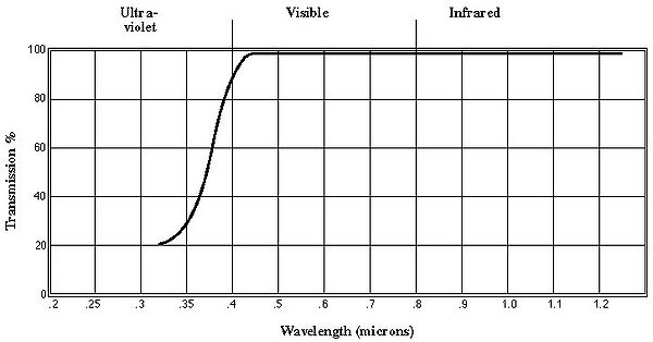
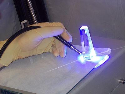
After some trial and error, the glue chosen was Norland Optical Adhesive 87. It is an adhesive that cures clear when exposed to ultraviolet light.
| Typical Properties of NOA 87 | |
|---|---|
| Refractive Index | 1.52 |
| Temperature Range | -30 C to 90 C |
| Viscosity @ 25C | 900-1500cps |
| Elongation at Failure | 13% |
| Modulus (PSI) | 209,700 |
| Tensile Strength | 4,880 |
| Hardness - Shore D | 50 |
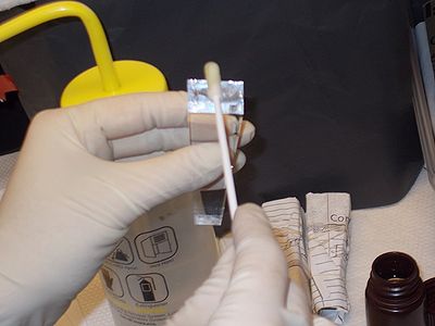
Once the glue was chosen, testing could begin. The goal was to determine the minimal amount of glue necessary for complete covering of the surfaces as well as to determine the length of time the UV light was needed in order to cure properly. During testing, we noticed that if the glue was not cured properly, clouds or bubbles would appear after 48 hours. The optimal time for curing was found to be 25 seconds from 4 sides of the light-guide and 20 seconds from the top.
Wrapping
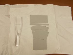
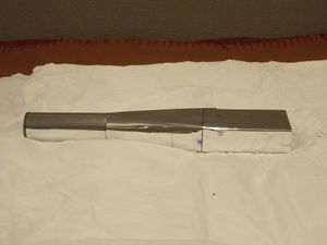
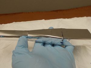
Because we wish to minimize wrinkling, a custom template has been made. Using Mylar, the light guide was wrapped using a trial and error process. From the finalized wrapping a template was constructed from non-corrugated cardboard to make it more practical to use.
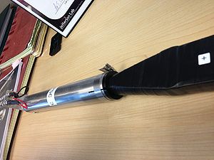
Once a template was completed, the light guide was wrapped with Mylar after being cleaned with distilled water and lent free cloth. Over the Mylar, a layer of Tedlar was added using the same template. The PS counter was then covered with a layer of black electrical tape and ready to be tested.
Cosmic Particle Detecting
Expectations
Because muons easily penetrate well into the Earth's surface, they will serve as a suitable means through which one can test a scintillator detector. Therefore, we hope to test these PS detectors in the same manner as we did with just the PMTs as outlined in Section 1. The difference will be that instead of the LED pulses, we will observe muon-interactions with the scintillator and amplified by the PMT. Each muon should, in theory, generate a readable pulse on the oscilloscope.
Testing
The set up for the testing, as was previously stated, is very similar to the testing of the PMTs. The image below portrays how each PS detector will be situated in the dark box. The dark box is used, of course, to minimize the all outside sources of radiation in an attempt to isolate only the cosmic radiation we are looking for.
Data
The oscilloscope was set to keep a history of pervious pulses in an attempt to find an average pulse amplitude and the trigger in each was set to -900 mV with a potential across the PMT of -1.3 kV.
Cosmic Particle Oscilloscope Readings
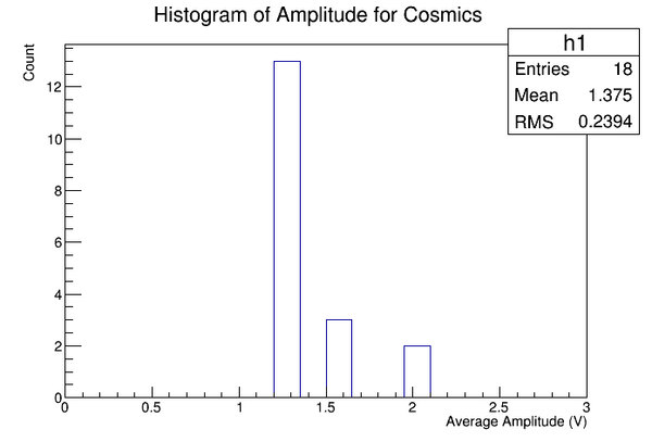
The data extracted from the readings in the link above is located in Figures 11-12.
|
|
Conclusions
From looking at the plots from the oscilloscope readings, one might notice an irregularity in the pulse shape of counters 2 & 8. The shape is unlike the other 16 counters in that they have a cleaner shape without the residual after-pulse that existed in the others. In these two counters, the oscilloscope data was collected after the 3 foot wires were cut down to about 12 inches. Now, this was done with all counters, but these two were the only ones tested after they were cut down. The extra wire seemed to add a secondary reflection pulse from the PMT that showed up even in the early testing of the PMTs by themselves (See Figure 2).
The data gathered from the testing of cosmic particles is satisfying in that the rise times appear relatively consistent between 3-4 ns and the average pulse amplitude is just over 1 V. Furthermore, that abnormal pulse shape that once existed in all counters is now eliminated since the shortening of the wires. There were significant sources of error here, in that the data was gathered visually from the images produce by the oscilloscope and not read digitally by electronics. This was done partially out of the need to ensure all counters were complete within the timeline, but mainly because the precise data would have been little use in the operation of the pair spectrometer once it was installed, calibrated, and running.
Assembly
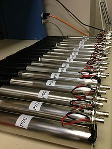
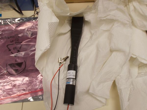
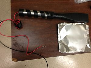
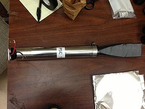
Once gluing, wrapping and testing were complete, magnetically sensitive parts of the detector (i.e. the PMTs) were wrapped in a mu-metal foil (See Figure 13) and placed in a mu-metal casing, held in place by a plastic collar, and sealed on the other end with a mu-metal end cap and mounting plate (See Figure 14). This assembly will serve as the PMT's primary magnetic shielding as well as facilitate installation in the hall. Once fully assembled, only the wrapped scintillator, part of the light guide, and connecting wires from the PMT are exposed beyond the mu-metal casing.
During assembly, there were a few instances where stress might be put on the glue joint, which may cause it to separate from the PMT. There have been 3 counters where this occurred during assembly, thus care must be taken not to put any excess strain on the glued joint.
Once each counter was complete, it was again tested for cosmics. During this test it was found that small yet chronic stress could also cause the PMT to separate from the joint. Therefore, it is imperative to use caution during assembly to assure that the joint remains free even from the mu-metal casing to avoid any unnecessary pressure.
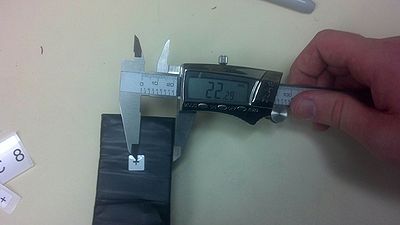
To facilitate alignment during installation, the centers of scintillators were marked using a set of digital calipers and printed labels. The scintillators are 60 mm x 44 mm but the layers of mylar, tedlar, and electrical tape add length to the overall measurement. Therefore all measurements are likely off by a fraction of a millimeter. This error should be trivial because the detectors overlap by 2 millimeters on each side.
Note: Many labels were printed off center so it is the actual "+" mark that should be used to identify the center.
Coincidence Counting
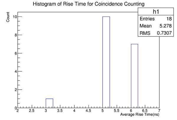
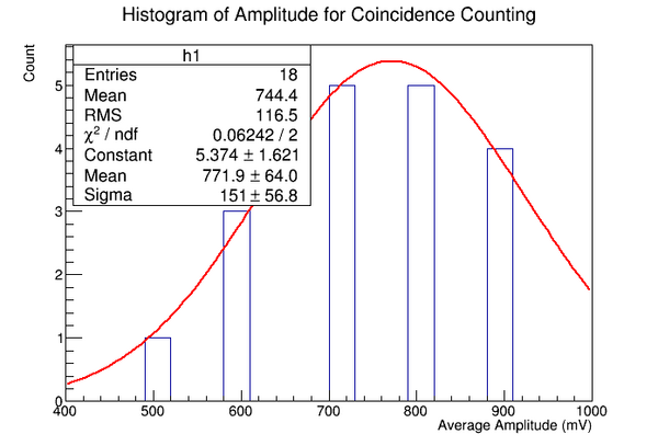
In the final testing of the low granularity pair spectrometer counters, a coincidence counting was done. Here, one counter was held 30 cm above another counter and at an angle of 90 degrees from each other where only the scintillators were overlapping. Here, the purpose was to ensure that there was no noise and that all counters were light tight. This is accomplished by using one counter as a trigger to initiate the reading on the second counter. Therefore, only cosmic particles were read on the oscilloscope and any other signal would be an indicator that the counter had problems either with not being light tight or with electrical noise.
Coincidence Counting Oscilloscope Readings
The data from the oscilloscope readings is displayed in Figures 23-24. As in Section 4, the data was gathered visually for the same reasons. However, the goal will eventually get precise coincidence data from ADC and TDC electronics before the counters are installed in Hall D. Unlike precise data from cosmics, the precise data from coincidence will assist in the calibration of the pair spectrometer.
|
|
Pre-Installation Testing (June/July 2014)
The PSCs, after being stored for a year, were retrieved and tested to account for possible wear during storage and transport. The first task was to test all eighteen PSCs for background noise using cosmic rays. The background check had a dual purpose; it allowed us to lower the signal threshold on the oscilloscope to check for light leaks and possible PMT noise.
Data
Data was collected from both background and coincidence tests. Background testing was used to isolate possible light leaks and PMT signal noise. Coincidence testing largely eliminates the background, therefore, it was used to obtain amplitude, rise time, and full width at half maximum. All non-variable potential testing took place at 1.35kV.
Background Test Data
To start the testing of the PSCs we first had to check for background noise. The types of noise we had a chance of encountering were thermionic emission from the cathode and dynodes, leakage currents, ionization phenomena, and light phenomena. Our main focus was to make sure each PSC was light tight and had no visible damage from the year of storage. We used a considerably lower threshold on the oscilloscope compared to the group last year, which made the background more noticeable. After testing all of the PSCs we determined there was no light phenomena, however, there may have been leakage current. The way we solved this will be discussed in the section "Background Voltage Tests." Below is a link to all the background tests at an input voltage of 1.35kV.
Cosmic Particle Oscilloscope Readings (Lower Threshold)
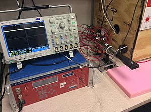
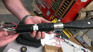
Figure 25. Shows the scintillator and light guide wrapped in black electrical tape so that it is light tight and the mu-metal screen encasing the PM so that no magnetic fields will effect the cascade of electrons. Figure 26. Shows the set-up to test for background. The device in the upper leftmost portion of the picture is an oscilloscope and below it is the high voltage supply we used throughout testing. The utmost care was used in handling the PSCs as seen in the picture.
Coincidence Test Data
The coincidence testing was started after the respective PSC was tested for background. Each test consisted of two PSCs, one which was the trigger or control variable (PSC-18) and one which was the experimental variable (Test PSC). This was a key task to complete in that it eliminated most background noise and gave data about each PSC. The data collected was signal amplitude, rise time, and full width at half maximum. Each of these were used to determine which 16 of the 18 PSCs will be used in installation in Hall-D, this will be covered in "Choosing PSCs." Below is a link to the pictures of each PSC coincidence test with an input voltage of 1.35kV.
Cosmic Particle Oscilloscope Coincidence Test
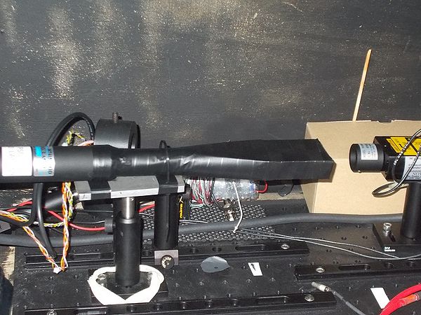
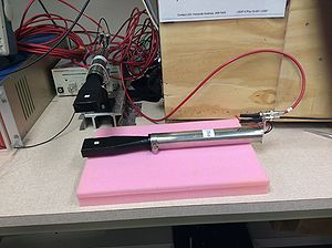
Figure 27. Shows the set-up for the coincidence testing. The PSC on the mount is the trigger PSC and the PSC on the pink foam pad is the test PSC.
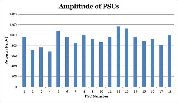
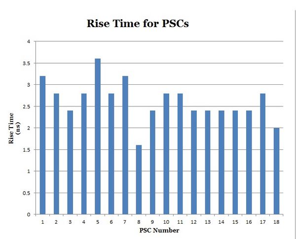
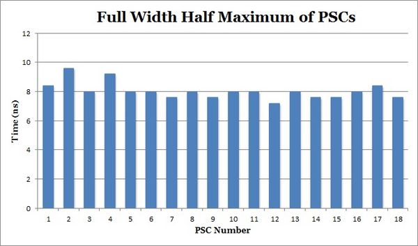
Figures 28, 29, and 30. Graphs of the three sets of data we obtained from the PSC coincidence tests.
|
|
|
Light Leakage Test
As stated before, light leakage was a major concern when testing the PSCs for background noise. To ensure that the there was no light phenomena, we tested several PSCs inside the sealed Dark Box and in a lit room. Below is a link to the two separate tests of each PSC.
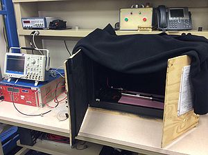
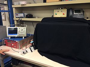
Figure 31. Shows the set up for the Dark Box Testing. Figure 32. Shows the sealed Dark Box.
Background Voltage Test
The background voltage tests were instigated so that we could determine, with a better confidence level, what exactly was producing the noise during the initial background tests. We lowered the input voltage of each of the three PSCs, below, to reduce the leakage current that we believed was the problem. In doing this, we found that it was, in fact, electrical noise that was creating the background. Below are the links to the three background voltage tests. The title of each picture will state at which input voltage it is at.
PSC-13 Background Voltage Test
PSC-18 Background Voltage Test
Coincidence Voltage Test
The coincidence voltage tests were commenced to allow us to gather data at different input voltage levels for several PSCs. The main purpose of doing this was to be able to assess the optimal input voltage level that is needed to maximize the efficiency of the PSCs that will be installed in Hall-D. Below are links to five different PSC coincidence voltage tests.
PSC-4 Coincidence Voltage Test
PSC-8 Coincidence Voltage Test
PSC-13 Coincidence Voltage Test
PSC-15 Coincidence Voltage Test
PSC-18 Coincidence Voltage Test
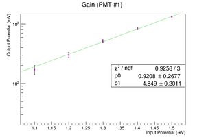
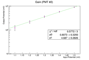
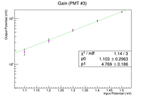
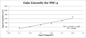
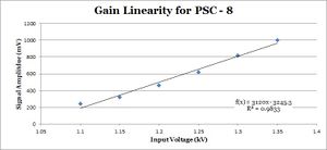
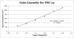
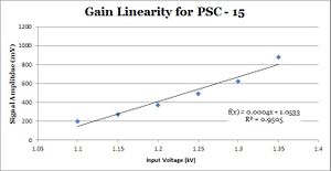
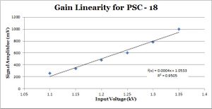
The gain linearity curves to the rightmost portion of the screen are the graphs made from inputting the data (table below) obtained from each of the coincidence voltage tests.
| PSC Amplitudes (mV) | ||||||
|---|---|---|---|---|---|---|
| PMT # | -1.1 kV | -1.15 kV | -1.2 kV | -1.25 kV | -1.3 kV | -1.35 kV |
| 4 | 160 | 210 | 300 | 360 | 500 | 680 |
| 8 | 240 | 320 | 460 | 620 | 820 | 1000 |
| 13 | 270 | 360 | 520 | 700 | 960 | 1120 |
| 15 | 200 | 270 | 370 | 490 | 620 | 880 |
| 18 | 260 | 340 | 480 | 600 | 780 | 1000 |
Choosing PSCs
| Amplitude Statistic Values | |
| Mean | 920 mV |
| Median | 940 mV |
| Mode | 960 mV |
| Variance (σ^2 | 16667 mV |
| Standard Deviation (σ) | 129 mV |
| Rise Time Statistic Values | |
| Mean | 2.6 ns |
| Median | 2.6 ns |
| Mode | 2.4 ns |
| Variance (σ^2) | 0.21 ns |
| Standard Deviation (σ) | o.46 ns |
| Full Width Half Max. Statistic Values | |
| Mean | 8.0 ns |
| Median | 8.0 ns |
| Mode | 8.0 ns |
| Variance (σ^2) | 0.39 ns |
| Standard Deviation (σ) | 0.62 ns |
Using the statistics from the previous tables we constructed a weighted scoring system for determining which PSCs would be best for the detector.We aimed for the most consistent data collection; with the most points being distributed to those within one standard deviation from the category mean value. In the table below three points were given if the values were within one standard deviation. Two points were allotted for two deviations, one for three deviations. Half point values were given if the measured values were not within one standard deviation, but were still favorable (i.e. rise time was shorter than average, amplitude greater than average). Those with the lowest values would be held in reserve as only sixteen of the eighteen PSCs are able to be installed.
| Weighted PSC Selection (mV) | ||||||
|---|---|---|---|---|---|---|
| PMT # | Amplitude | Rise Time | FWHM | Total | ||
| 1 | 3 | 2 | 3 | 8 | ||
| 2 | 2 | 3 | 1 | 6 | ||
| 3 | 2 | 2 | 3 | 7 | ||
| 4 | 2 | 3 | 2 | 7 | ||
| 5 | 2 | 1 | 3 | 6 | ||
| 6 | 3 | 3 | 3 | 9 | ||
| 7 | 3 | 2 | 3 | 8 | ||
| 8 | 3 | 1.5 | 3 | 7.5 | ||
| 9 | 3 | 2.5 | 3 | 8.5 | ||
| 10 | 3 | 3 | 3 | 9 | ||
| 11 | 3 | 3 | 3 | 9 | ||
| 12 | 2.5 | 2.5 | 2.5 | 7.5 | ||
| 13 | 2.5 | 2.5 | 3 | 8 | ||
| 14 | 3 | 2.5 | 3 | 8.5 | ||
| 15 | 3 | 2.5 | 3 | 8.5 | ||
| 16 | 3 | 2.5 | 3 | 8.5 | ||
| 17 | 3 | 3 | 3 | 9 | ||
| 18 | 3 | 2.5 | 3 | 8.5 | ||
The lowest weighted values are "6," therefore PSC 2 and 5 will be held in reserve.
| Amplitude Statistic Values Post Elimination | |
| Mean | 924 mV |
| Median | 940 mV |
| Mode | 960 mV |
| Variance (σ^2 | 14111 mV |
| Standard Deviation (σ) | 119 mV |
| Rise Time Statistic Values Post Elimination | |
| Mean | 2.6 ns |
| Median | 2.4 ns |
| Mode | 2.4 ns |
| Variance (σ^2) | 0.16 ns |
| Standard Deviation (σ) | 0.40 ns |
| Full Width Half Max. Statistic Values Post Elimination | |
| Mean | 8.0 ns |
| Median | 8.0 ns |
| Mode | 8.0 ns |
| Variance (σ^2) | 0.2 ns |
| Standard Deviation (σ) | 0.44 ns |
Installation
EXPECTED JUNE-JULY 2014
Materials
The materials used throughout the PSC installation process.
• Electrical tape
• ~10 Zip Ties
• 32 Uni-strut clamps
• 1 Bubble Level -1m
• 1 Bubble Level -1ft
• 1 Pair of scissors
• 1 Box cutter
• Ruler
• Measuring tape
• Camera
• Insulation (Neoprene Rubber ~1.5mm thick)
• Nylon String
• 1 7/16" Wrench
• 1 1/2" Wrench
PSC Insulation Assembly
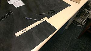
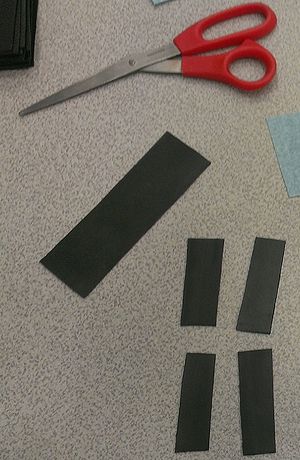
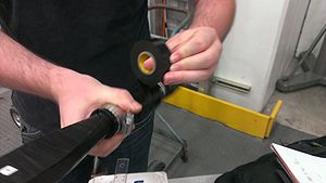
The machining of the four sets of transverse uni-strut bars was not as precise to one another as would be prefered. There were minor errors in the distance of each set perpendicularly from the center-line position. This caused problems in the depth between the scintillator locations, namely, the north side rack and south side rack had different z-axis positions for the scintillators. To adjust for this the insulation was not applied uniformly to every PSC, but differed based on the rack it was clamped to.
The north rack had a significantly larger gap between the scintillators, creating a problem. To remedy this problem, as best we could, the insulation between the PSC mu-metal casing and the sets of uni-strut bars was kept to a minimum. Only a single thick layer of vinyl electrical tape was wrapped completely around the tube to prevent any scratching or grounding of the PSCs. This made it so we were able to keep the gap to a maximum of 2-4 mm. The southern rack had considerable less space between the scintillator heads compared to the northern rack. This meant that the minimal insulation of the other PSCs would not work in this case. To compensate for the distance we added two thin strips of neoprene rubber (~1.5mm in thickness, and 5cm long) where the uni-strut bars met the PSC metal casing. These neoprene rubber strips were held in place with two lengthwise strips of electrical tape and then vinyl electrical tape was wrapped around the circumference of the entire PSC, similar to the north rack design.Using this method we were able to both insulate the detectors and provide enough space to ensure the scintillator heads were not applying stress to one another.
Installation
Procedure
1. Gather all materials listed.
2. Make proper measurements.
• Distance between each uni-strut on top set and bottom set.
• Distance between top set of uni-struts and bottom set of unistruts.
• Distance of height on the frame which intersects the beam line.
• Distance from beam line to first PSC.
• Width of uni-strut clamp.
3. Cut thirty-two strips of insulating material equal to circumference of each PSC and ~1 cm greater width than that of the clamp.
4. Apply a strip of electrical tape lengthwise on top and bottom of insulating material, leaving an excess of one cm on the left of the material for fastening.
5. Wrap insulating material on PSC at proper clamp position, determined through measurements.
6. Place a PSC at the correct distance from the beam line (provided by Sasha, approximately 22cm) making sure to line up the center mark on the scintillator parallel to the beam line.
7. Tighten clamps by hand.
8. Measure and adjust center position if needed.
9. Tighten clamps firmly with wrench, being careful not to stress the mu-metal.
10. Repeat from step “5.” with the next seven PSCs, making sure to overlap each successive PSC scintillator 2mm with the previous PSC scintillator.
11. Successive scintillators should alternate between top and bottom rack positions.
12. Use bubble level to maintain center line position.
13. Run cabling to each respective PSC making sure to not leave excess wire by tying off with zip ties.
14. Ensure the power supply is not delivering high voltage while fastening and connecting.
15. Make adjustments as needed.
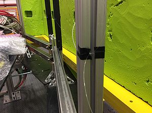
The insulated PSCs were organized according to the following translation diagram (Figure 40. Below). We tied a nylon string at the center beamline position and used a one-meter bubble level to make sure the string was at the necessary position. This string provided a mark for the center position stickers placed on each scintillator head to ensure a more accurate installation.
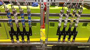
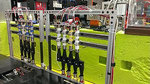
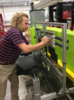
One person held the PSC in position, making sure that the faces were level and its height was aligned with the nylon string while the second person then proceeded to fasten and tighten each uni-strut clamp. Using this method we could ensure than future adjustments would be minor. Once the PSCs were attached, we threaded cable via the cable racks below the floor from the splitter to a narrow hole near the bottom of the pair-spectrometer frame. The low-granularity then had both its power and signal cables divided into two groups of eight and fasted along the legs of the frame while special care taken to leave excess cable should it be needed, but not enough to become intrusive. We then connected the cables to the necessary ports on each PSC and proceeded to testing.
Post Installation Testing
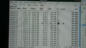
After each PSC was mounted to the racks, we proceeded to test them using cosmic radiation. This test was designed much the same way as the pre-installation testing. To turn on the input voltage in post-installation testing we had to access the control system for Hall D's voltage system. Once the terminal was open we had to type one line: telnet u1-9-top 1527. This put us in the Hall D log-in page which we proceeded to log-in to. From this point we went to the Main heading and clicked on Channels (Figure 44 Below). Here is where we could turn voltage to the channel either on or off and monitor both current(IMon) and voltage (VMon) being applied to the channel.
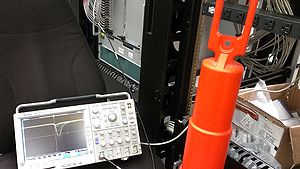
We used the same materials, and same general settings for the oscilloscope (Figure 45 Below). Since both of the background testing practices were similar we were able to take the previously collected data taken at 1.25 kV for the pre-installation background testing and compare it to the newly collected post-installation data.
Post Installation Background Testing
| Monitored Voltage and Current | ||||||
|---|---|---|---|---|---|---|
| Ch. # (PSC #) | VMon (V) | IMon ( μA) | ||||
| Ch. 00 (PSC 1) | 1251.0 | 187.0 | ||||
| Ch. 01 (PSC 18) | 1251.0 | 185.0 | ||||
| Ch. 02 (PSC 3) | 1250.5 | 187.5 | ||||
| Ch. 03 (PSC 4) | 1250.5 | 186.5 | ||||
| Ch. 04 (PSC 17) | 1250.5 | 186.5 | ||||
| Ch. 05 (PSC 6) | 1250.5 | 187.5 | ||||
| Ch. 06 (PSC 7) | 1250.5 | 186.0 | ||||
| Ch. 07 (PSC 8) | 1250.5 | 186.5 | ||||
| Ch. 08 (PSC 9) | 1251.0 | 185.5 | ||||
| Ch. 09 (PSC 10) | 1251.0 | 185.5 | ||||
| Ch. 10 (PSC 11) | 1250.5 | 186.5 | ||||
| Ch. 11 (PSC 12) | 1251.0 | 186.5 | ||||
| Ch. 12 (PSC 13) | 1250.5 | 188.0 | ||||
| Ch. 13 (PSC 14) | 1251.0 | 186.5 | ||||
| Ch. 14 (PSC 15) | 1250.0 | 187.0 | ||||
| Ch. 15 (PSC 16) | 1250.5 | 185.5 | ||||
| Average | 1250.7 | 186.47 | ||||
