Difference between revisions of "Study noise inside FCAL"
From GlueXWiki
(Created page with "<gallery> Image:test_div_setup.jpg | Fig. 1 Position of the lead glass module inside the dark room </gallery>") |
|||
| (4 intermediate revisions by the same user not shown) | |||
| Line 1: | Line 1: | ||
<gallery> | <gallery> | ||
Image:test_div_setup.jpg | Fig. 1 Position of the lead glass module inside the dark room | Image:test_div_setup.jpg | Fig. 1 Position of the lead glass module inside the dark room | ||
| + | </gallery> | ||
| + | <gallery> | ||
| + | Image:test_fcal_noise.jpg | Fig. 2 Signals from the FCAL base | ||
| + | </gallery> | ||
| + | <gallery> | ||
| + | Image:test_bypassed1.jpg | Fig. 3 Insert: noise in the divider with the bypassed amplifier | ||
| + | Image:test_bypassed2.jpg | Fig. 4 | ||
| + | </gallery> | ||
| + | <gallery> | ||
| + | Image:test_amp1.jpg | Fig. 5 Insert: noise in the divider with amplifier | ||
| + | Image:test_amp2.jpg | Fig. 6 CAN Bus enabled | ||
| + | Image:test_amp3.jpg | Fig. 7 FCAL voltages and LEDs are on | ||
</gallery> | </gallery> | ||
Latest revision as of 10:34, 9 December 2022
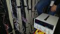
Fig. 1 Position of the lead glass module inside the dark room

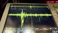
Fig. 2 Signals from the FCAL base

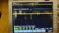
Fig. 3 Insert: noise in the divider with the bypassed amplifier
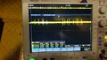
Fig. 4


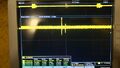
Fig. 5 Insert: noise in the divider with amplifier
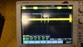
Fig. 6 CAN Bus enabled
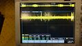
Fig. 7 FCAL voltages and LEDs are on


