Difference between revisions of "Visual inspection and repairing of lead glass modules"
(→Disassemble Lead Glass Module) |
(→Disassemble Lead Glass Module) |
||
| (4 intermediate revisions by the same user not shown) | |||
| Line 6: | Line 6: | ||
Image:glass_strap.jpg | Fig. 3 Remove steel strap assembly | Image:glass_strap.jpg | Fig. 3 Remove steel strap assembly | ||
Image:glass_sc1.jpg | Fig. 4 Remove silicon cookie from the PMT side of the glass bar | Image:glass_sc1.jpg | Fig. 4 Remove silicon cookie from the PMT side of the glass bar | ||
| − | Image: | + | Image:glass_unwrap.jpg | Fig. 5 Remove wrapping from the module |
</gallery> | </gallery> | ||
| Line 17: | Line 17: | ||
Step 3. Remove steel strap assembly holding together the PMT housing and lead glass block | Step 3. Remove steel strap assembly holding together the PMT housing and lead glass block | ||
| − | Step 4. Remove silicon cookie (note the cookie may stick to the glass block) | + | Step 4. Remove silicon cookie (note the cookie may stick to the glass block; use a wood stick to scrub if needed) |
| + | |||
| + | Step 5. Remove aluminized mylar wrapped around the glass block. Note, the Al Mylar thickness is about 13 um; the Mylar joint is positioned under the strap (no sticky tape is used on the joint) | ||
Latest revision as of 22:54, 17 October 2022
Disassemble Lead Glass Module
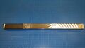
Fig. 1 Lead glass module: Lead glass block wrapped with Al mylar. PMT housing is attached to the block using steel strap assembly.
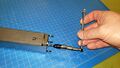
Fig. 2 Unscrew flange from the PMT side
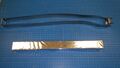
Fig. 3 Remove steel strap assembly
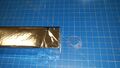
Fig. 4 Remove silicon cookie from the PMT side of the glass bar
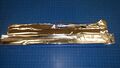
Fig. 5 Remove wrapping from the module


Step 1: Inspect lead glass module (see corresponding section) to make sure the the module
has to be disassembled.
Step 2. Loose screws on the flange attached to the PMT housing
Step 3. Remove steel strap assembly holding together the PMT housing and lead glass block
Step 4. Remove silicon cookie (note the cookie may stick to the glass block; use a wood stick to scrub if needed)
Step 5. Remove aluminized mylar wrapped around the glass block. Note, the Al Mylar thickness is about 13 um; the Mylar joint is positioned under the strap (no sticky tape is used on the joint)