Difference between revisions of "Minutes-1-15-2009"
From GlueXWiki
(→Cathode Planning) |
(→Cathode flatness measuring system) |
||
| (One intermediate revision by the same user not shown) | |||
| Line 66: | Line 66: | ||
* Location: M:\halld\Individual-Schedules\FDC or for more sophisticated | * Location: M:\halld\Individual-Schedules\FDC or for more sophisticated | ||
folks, /u/group/halld/Individual-Schedules/FDC | folks, /u/group/halld/Individual-Schedules/FDC | ||
| + | At present we are sticking to the schedule reasonably well across the | ||
| + | board. | ||
- Progress updates: | - Progress updates: | ||
* The cathode edge cutting system has been assembled. A few last | * The cathode edge cutting system has been assembled. A few last | ||
| Line 129: | Line 131: | ||
==Cathode flatness measuring system== | ==Cathode flatness measuring system== | ||
| − | - Documentation of the system continues. See the [http://www.jlab.org/Hall-D/software/wiki/index.php/HOWTO_Analyze_a_FDC_Flatness_Scan FDC | + | - Documentation of the system continues. See the [http://www.jlab.org/Hall-D/software/wiki/index.php/HOWTO_Analyze_a_FDC_Flatness_Scan FDC wiki page] for details. |
==Spacer Design== | ==Spacer Design== | ||
Latest revision as of 17:26, 15 January 2009
FDC Weekly Meeting
Date: January 15, 2009
Participants: Daniel, Micah, Simon, Mark I., Mark S., Chuck, Brian, Beni, Kim, Roger, Eugene, Bill
Next Meeting: January 22, 2009 @ 1:30 p.m.
Contents
Full-Scale Prototype Updates
 - Procurements:
    * Roger will check with the company for the rigid-flex assembly
      order. He stated that he believes that the boards are now in
      production.
    * The replacement order for the Rohacell should arrive any day now.
 - Wire QA studies:
    * We got the SEM photographs from the field wire scans from Olga
      Trofimova. Brian will look into having them complete the EDS
      measurements so that we can get some mass spectroscopy done. DSC
      provided an example to Brian based on work done for Hall B. The
      issue is that this could not be done with our pre-mounted wire
      samples. Brian will provide additional samples of our tungsten and
      CuBe wire for this work.
    * Brian will prepare a final QA report with photos and test results
      for all wires when all studies are complete.
 - Mark S. is also responsible for upkeep of the list of procurements for
   the full-scale prototypes.
      * Location: M Drive/halld/Electronics, or for more sophisticated folks,
        /u/group/halld/Electronics.
 - The Hall A folks have inquired about use of the clean tent. Brian will
   find out more about their requirements and time line and we will work
   to get them in at a convenient time.
Wire Frame Construction
 - Brian and Mark have completed 5 G10/Rohacell laminates. The laminates
   have been planed to the required thickness by the JLab machine shop
   and the thicknesses have been checked by them compared to our required
   tolerances. One of the laminates exhibited some local delamination at
   4 places along its outer diameter. The other four laminates looked
   great. Bill suggested that we increase the epoxy thickness slightly
   during construction.
 - The next stage of machining of the laminates is to add the through-holes
   and the pockets for clearance of the rigid-flex assemblies. This work
   be done by Monday and the boards returned to us. Mark will do some
   thickness checks and report the findings to DSC. Once this work is done,
   we will move on the construction of the first wire frame.
 - After QA checkout and review of procedures, we will move immediately
   to construction of the remaining wire frames. We hope to complete
   construction of all four frames for IUCF by the end of next week
   (Jan. 23). Hopefully we are on target.
 - We should have two construction stations fully available for this
   work. One will be located in the clean tent and the other in the
   JLab machine shop viewing room.
 - We will be in contact with the JLab machine shop so that IUCF can be
   kept up to date on our plans for shipment.
 - Kim needs to complete the PCB stuffing/cleaning document. This should
   be done by the middle of February.
 - We had talked about sending Bill to IUCF to learn the ropes on wire
   winding. This needs to be organized internally and with the IUCF
   folks. DSC will talk with Elke about organization.
Cathode Planning
- We reviewed the cathode R&D timeline. Folks are reminded to pass on
progress updates to Chuck every Wednesday. The current schedule is
being kept on the mdrive at:
* Location: M:\halld\Individual-Schedules\FDC or for more sophisticated
folks, /u/group/halld/Individual-Schedules/FDC
At present we are sticking to the schedule reasonably well across the
board.
- Progress updates:
* The cathode edge cutting system has been assembled. A few last
odds and ends will be installed this week and then we will do
some test cuts. We should have results to report by our next
FDC meeting.
* The construction document is not yet under way formally, but
Bill is gathering drawings that are needed and Brian and Mark
will be taking photos of the construction work that is going on
now.
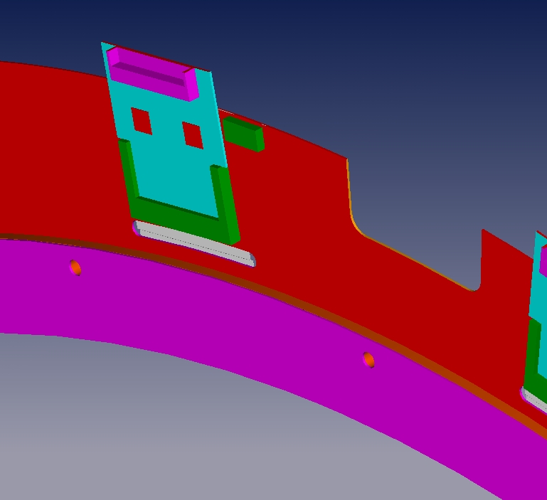
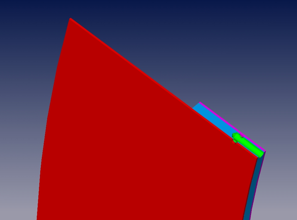
* Brian and Mark are now starting work on construction of the
full-scale cathode sandwich. They are now making up two cathode
frames. The details are contained in the assembly drawing. You can
see that the frame is made from a large G10 annulus and a thin
Rohacell + G10 annulus. After the foam and the large G10 annulus
are laminated, the piece will go to the machine shop to plane it
to the proper thickness and to include the gas holes. A couple of
things have us concerned at the present moment. The first is that
the assembly drawing reveals mechanical strength worries. The
small G10 + foam annulus does may be undersized, but its radius is
limited by the daughter board space requirements. Also note that the
gas holes are cut radially into the foam piece further weakening it.
There are up to 25 of this to allow equalize the gas pressure on
either size of the cathode. The plan is to make these cathodes as realistic
as possible to study their performance with a realistic Kapton cathode
board tensioned to the expected tension of 300 to 400 N/m.
* We believe that we have a viable way of connecting the external
ground to the cathode boards and to the ground plane between cathodes.
Mark has made us a little prototype and passed it around. We would
like to get feedback from Fernando on the design. The nominal design
includes tabs on the cathode boards and ground planes that fold
over the frames onto which the connector pigtails are attached via
conductive glue.
* Eugene is continuing his study of the artwork distortions in the
sample 2-micron cathode board. The board was tensioned to an average
value of about 500 N/m. In the dimension perpendicular to the strips,
the board elongated about 0.3%. The tension on the board relaxed
20% after the first 24 hours and has remainded constant for more
than a week now. It is not clear if this is a feature of the board
or of the tensioner. The stretching in the coordinate along the
strips is about 0.15%.
* The work of Eugene led us to discuss how to procede with the cathode
design. DSC believes that these measured numbers (which were done
with the polyimide that we will have in the final detector, but were
not on a very asymmetrical piece) should be used as upper limits for
the stretching (as will will tension to an average value of 300 N/m).
Perhaps we should scale the artwork by -0.3% across the strips and
-0.15% along the strips to take out the lion's share of the distortion.
We then might want to measure the strip distortion to make tracking
corrections if necessary. More discussion on this is needed. However,
Roger does need to work on the board design to move traces away from
through holes to allow for up to about 2 mm of stretching (max) along
a radius.
* Roger asked when we plan to place the next cathode order and what
material we want. The answer is that we would like to place the
remainder of the order by the middle of February. While we don't
have an answer yet, we most likely would like to purchase all 2 micron
stock. If there is an issue with availability of materials, we would
not wish to delay delivery and we would take a mixture of 2 micron
and 5 micron stock. We will move to make a decision very shortly.
Roger will be in contact with Allflex to give them a head's up on
where we are.
Cathode flatness measuring system
- Documentation of the system continues. See the FDC wiki page for details.
Spacer Design
 - Bill has completed the prints for the spacer construction and will pass
   them onto the machine shop shortly.
Stack Assembly Procedures
 - DSC, Brian, and Bill will work to finalize the stack assembly construction
   document that has been prepared.  This document should be in place before
   we get too far in the construction process.
 - Bill has found some plastic threaded rods that could be used to
   compress the stack.  We will be receiving some samples shortly and
   will carry out some loading tests.
Cooling System Tests
 - Fernando is in the process of writing up the results from his cooling
   system studies.  Stay tuned for the GlueX note.
 - Bill has done some ANSYS modeling to better study the connector that
   goes from the daughter board card to the cooling loop.  These will be
   added to Fernando's note.
Documentation
 - Roger needs to prepare a document for QA/stuffing/cleaning for the
   cathode boards and a similar document for the cathode daughter
   boards and ground boards.
Small-Scale Prototype
 - We will be moving the FDC cosmic ray test stand from the Test Lab back
   to the EEL building. This move should be completed in the next 6 months
   or so.
Work List
 - The FDC short-term work list has been posted on the FDC web site.
   This is continually being updated and DSC welcomes any feedback or
   comments from the group.
Minutes prepared by Daniel. Send any comments or corrections along.