Difference between revisions of "First look at TOF calibration"
From GlueXWiki
| Line 18: | Line 18: | ||
*# for each event plot for each paddle in plane k: <math> MT^{n}_{plane k} + MT^{i}_{plane j} </math> | *# for each event plot for each paddle in plane k: <math> MT^{n}_{plane k} + MT^{i}_{plane j} </math> | ||
*# [[File:example_mtdiff.gif|400px]] | *# [[File:example_mtdiff.gif|400px]] | ||
| + | *# and after using the correction timing conversion: | ||
| + | *# [[File:mantimediff_goodtiming.png|400px]] | ||
*# fit the meant time peak of each projection: | *# fit the meant time peak of each projection: | ||
*# [[File:Fit_projection_example1.gif|400px]] example 1 | *# [[File:Fit_projection_example1.gif|400px]] example 1 | ||
Revision as of 08:38, 17 April 2015
First Look
- first select data sample with the following conditions:
- only consider hits within 50ns of the timing peak both for ADC data and TDC data
- only consider paddles that have hits on both ends
- take care of the 6fold trigger timing shift in the TDC (24ns window)
- Do a rough determination of the walk correction by using the time in the ADC as reference.
- calculate Time difference:
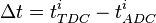
- calculate Integral: I = pulse_integral - pulse_pedestal*nsamples
-
- Note: the minimum ionizing peak is between 6000 and 10000
- After using the correct timing conversion of 23.4375 ps/bin the following much narrower distribution is achieved
-
- calculate Time difference:


- Do mean time comparison between different planes
- calculate MeanTime of Paddle i in plane j:
- calculate MeanTime for all Paddles n in plane k:
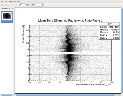
- for each event plot for each paddle in plane k:
-
- and after using the correction timing conversion:
-
- fit the meant time peak of each projection:
-
 example 1
 -
 example 2
 - Do this for each paddle in the first plane as reference paddle.
- Choose one paddle in the first plane as THE REFERENCE PADDLE
- Calculate the difference between the fit results of each paddle in the first plane w.r.t. THE REFERENCE PADDLE and fit the distribution
-
 average difference of mean time to REFERENCE PADDLE
 - Now we have offsets for the Mean-Time for all Paddles w.r.t. THE REFERENCE PADDLE
- calculate MeanTime of Paddle i in plane j:


- Do time difference comparison of one paddle with the paddle number in the other plane
- calculate time difference:
- plot this time difference vs. paddle number of paddles that got hit in the other plane
-
- again look at each projection and fit the
 peak
peak -
 example fits
 - now one can also plot the fit results as a function of paddle number. The inverse slope is the speed module paddle pitch
-
- one can also plot the difference between symmetric paddles around the beam hole
-
 choose the intersection at zero for the time difference offset
- calculate time difference:


- Now we have offsets for time difference (TD) and mean time (MT)
- offset for the left pmt:
- offset for the right pmt:
- as a bonus we get the effective speed of light for each paddle.
- offset for the left pmt: