Module assembly
From GlueXWiki
Comcal module assembly procedure
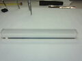
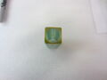
PWO crystal before wrapping
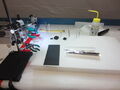
Wrapping bench
PWO crystal into ESR pre-shaped form
Sticking ESR form with 50um kapton
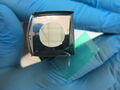
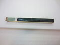
Front face of the assembly
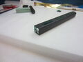
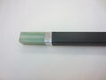
Wrapped crystal
Front face of PMT housing (PWO crystal contact area)


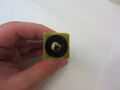
Front face of PMT housing with PMT inserted
PMT housing
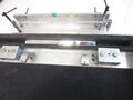
Strip brass assembly with crystal and PMT housing
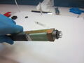
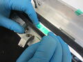
PMT and nu-metal insertion into housing


- Step 1. Make sure appropriate protective equipment is used (Gloves)
- Step 2. Make sure the working space clear. Light is on. Prepare preshaped ESR and precut Tedlar
- Step 3. Take crystal from locker. Put entry into the table (Date, name. Crystal number, module number etc.)
- Step 4. Unwrap the crystal and put it on top of the foam block.
- Step 5. Clean crystal with 50/50 solution and cleanroom paper. Clean ESR with the duster or with 50/50 if needed. Remove the crystal label.
- Step 6. Put crystal into ESR pre-shaped form. Take ESR and crystal put them into wrapper slot. Press down firmly providing pressure on bottom and sides.
- Step 7. Take 1 inch piece of tape. Bring closure of ESR together using your fingers and tape 3 times (front, middle, back) . Add 4th if needed.
- Step 8. Take wrapped crystal put onto the plate. Write crystal serial number on ESR with black marker
- Step 9. Take tedlar pre-cut film. Take crystal and place it on top of the tedlar making sure that 2mm of extra tedlar material on front. Tape side goes down. Press crystal into the slot. Repeat step 7 with tedlar.
- Step 10. Put crystal on foam block. Take protective plate and gently place it at upstream end. Make four 2mm incisions in the corners of tedlar.
- Step 11. Put ESR front end make sure round hole is in the middle. Clear protecting side of ESR goes down.
- Step 12. Fix crystal vertically with clamps and L-stand. Make sure that upstream end of the crystal facing up.
- Step 13. Tape corners down and trim excess tape (use green tape).Make sure that tape not overlap the central hole in ESR front face.
- Step 14. Make sure the crystal is not free sliding in the wrap. Make sure that tedlar is not damaged.
- Step 15. Prepare G-10 housing with tape, PMT, brass strip, nu-metal plate, optical grease, screws, wrapped crystal
- Step 16. Make sure you fill output table.
- Step 17. Connect G10-housing and downstream face of the crystal. Tedlar should be around housing. Tape tedlar edge tight to G-10 housing. Tedlar edge should be in the middle of the tape.
- Step 18. Place straps on to housing+crystal assembly. Tape side should be up not under the brass
- Step 19. Prepare four set screws. Insert them into back flange thread holes.
- Step 20. Using short leg of the Allen key tighten set screws alternately till Allen key start deflecting (5mm)
- Step 21. Wrap nu-metal around PMT. Tape it at the top and bottom. Clear front face of PMT and apply 0.1 mm2 of optical grease. Insert PMT into housing pushing twist.
- Step 22. Look into upstream end hole and check optical contact (bubbles, position of PMT and etc.)
- Step 23. Put PMT pressure plate then insert corner screws.
- Step 24. Wright down into the log table crystal serial number, PMT serial number, date of assembly, initials.
- Step 25. Place assembled module to the storage area for quality assurance