Back to Background Rate Studies
Detector Configuration
- Double-Hit Resolution: 250 ns
- Threshold: 1 keV
- Strip Threshold: 5 mV
- Maximum Number of Hits: 100
- Dead Zone Radius: 3.5 cm
Items for Discussion
- Is the maximum number of hits coded into the simulation sufficient for the FDC? If it is applied at the event level, 100 hits is probably not enough.
- How relevant is the increased background as a function of downstream position of the package?
- Does this need to be considered when optimizing package placement?
- Do/Should the dead regions for each package vary in size depending on downstream location?
- Cathode strip readout energy looks to be incorrect?
- Explore dependence of rate on dead zone size.
Plots
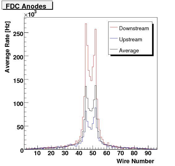
A plot of the rate as a function of anode wire number for the most dowstream anode plane (blue), the most upstream anode plane (red), and the average rate (black).
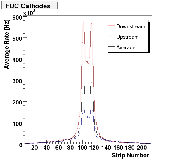
A plot of the rate as a function of cathode strip number for the most dowstream cathode plane (blue), the most upstream cathode plane (red), and the average rate (black).
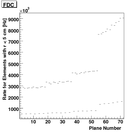
A plot of the rate within 5 cm of the beam axis as a function of the plane number if the FDC. Planes for which N%3 == 2 are anodes, all other planes are cathodes. The notable increase in rate for the downstream chambers could be due to opening of charged particles in the relatively weaker field.
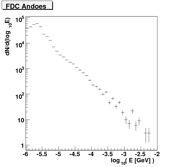
A double-log plot of the energy of all hits on anode wires in the FDC. The spectrum cuts off at 1 keV due to the GEANT threshold.
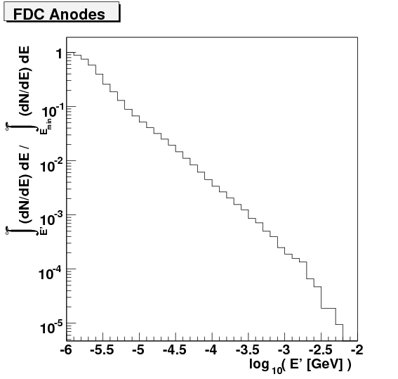
The integral of the plot above.
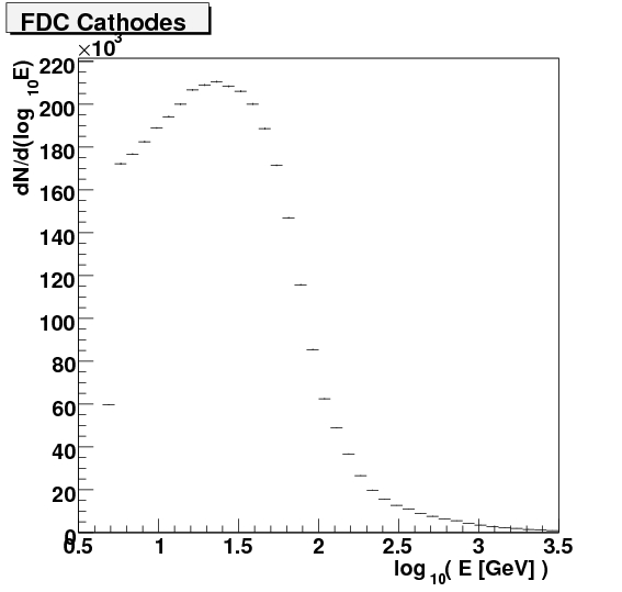
A double-log plot of the energy of all hits on cathode strips in the FDC. This looks buggy or else the units aren't quite as advertised.
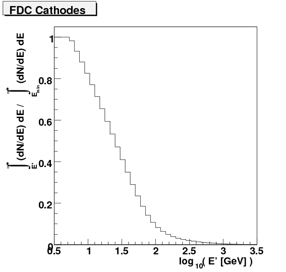
The integral of the plot above.


